Hi all 🙂 , how are you ? 😉
I want to build a simple stereo preamp with gain of X5-X6
Something like this preamp stage in Marantz 2226 (this stage is before the tone control )
i did a search here but I founded only complicated preamps
I want preap with only 4 BJT transistors , 2 to each side .
do you have a recommedation for me ? or you think I can build this marantz 2226 stage . and it will be just fine ?
thanks have a nice day .
Attachments
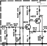
Circuit around RE05, RE07 & RE08 does not look right to me!
Anyway, just out of interest: why are you limiting your design to the use of 'just' two BJTs per channel? However I agree that less is more (sometimes)...
Andy
Anyway, just out of interest: why are you limiting your design to the use of 'just' two BJTs per channel? However I agree that less is more (sometimes)...
Andy
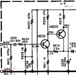
But without short circuit across RE08, should work OK, and give a gain of about x3.7 if using for example ZTX651 / ZTX751 for the transistors.
Andy
Andy
Looks like a half of diamond buffer. Do the proper diamond buffer and throw the caps away.
Two additional BJTs are better than two additional coupling caps. Much better.
edit: ahh, you need gain. I always though of preamps as unity-gain devices....
Two additional BJTs are better than two additional coupling caps. Much better.
edit: ahh, you need gain. I always though of preamps as unity-gain devices....
Last edited:
so 8 BJT transistor will ok ( 4 to each side )
but the problem is that I have only positive 35V + , i can't give negetive volt .
actually i can but i want to avoid it and only use positive V
can you recommend me schema for that ? thanks
but the problem is that I have only positive 35V + , i can't give negetive volt .
actually i can but i want to avoid it and only use positive V
can you recommend me schema for that ? thanks


thanks , look simple as I want 🙂 ,
but how I adjust it to the 35 V ?
can you do that for me ?
I'll see what I can come up with 🙂
Be later today...
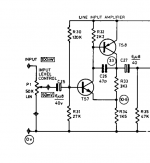
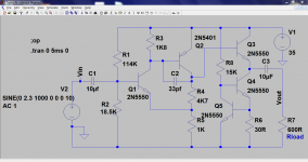
This should work,
R30 = 120K
R31 = 15K
R32 = 1K8
R33 = 4K7
R34 = 1K
Points to note.
The gain equals (R33 + R34)/R34 so this gives around 5.7 voltage gain.
The bias network sets the output voltage "midpoint" which should be around half the supply (the collector of TS8) so if you want to add or alter anything then make R31 a preset for initial setting and then replace with a fixed resistor. The 47pf cap is OK.
Yes... but it's not always as simple as that. I'll post some examples to show why.
Do you use or have LTspice ?
Also what is this preamp feeding "load wise" ?
Do you use or have LTspice ?
Also what is this preamp feeding "load wise" ?
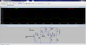
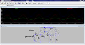
Look at the pictures here. They show the points Vin and Vout and Vout_main. Vout_main is just Vout but after a cap to block the DC.
So three examples.
The first one "clipping" shows the output of the amp with it overdriven. You can see it clips pretty well symetrically.
Second one "Clipping 10K Load" is with a 10K load and that really alters things.
Third one "Equal Clipping" is with R2 altered to "fiddle" the clipping under load so it clips symetrically. This is for a 10K load and in practice you can see there is still a good swing available.
An easy option is to just add a third transistor as an emitter follower if you wanted. Circuits like this can be eleborated on indefinately but the basic two transistor amp is a sonic delight as the distortion is mainly even harmonic.
Attachments

thanks molly ,
i assembled the pre ,
I checked the collector ts8 transistor volts and its 12V DC both side .
the pre work fine i think with no distortion or maybe with very low dist' .
by the way it sound good 🙂 .
so we need to change r31 bias resistor ?
thanks moly , i have to go for an hour i will come back /
i assembled the pre ,
I checked the collector ts8 transistor volts and its 12V DC both side .
the pre work fine i think with no distortion or maybe with very low dist' .
by the way it sound good 🙂 .
so we need to change r31 bias resistor ?
thanks moly , i have to go for an hour i will come back /
Aim to get the collector of TS8 at around half the supply voltage by altering either R31 or R30 (or both... depends what you have available) and it should be fine.
I'll put an even better example together for you later (maybe tomorrow) with a simple buffer stage on the output. (Which is a good excuse for me to practice my LTspice skills 🙂)
I'll put an even better example together for you later (maybe tomorrow) with a simple buffer stage on the output. (Which is a good excuse for me to practice my LTspice skills 🙂)
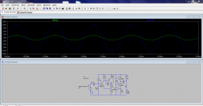
Here you go. Two simple buffers.
The first is just an emitter follower and the second adds a constant current load in place of the normal load resistor. Notice how this one can swing the full output voltage into a load of 600 ohms. The penalty for this (on both buffers) is a higher current consumption. If you know what load you are driving then you can tailor the design to suit.
The DC voltage at the output (end of C3) is 21 volts and that gives the maximum swing into 600 ohms. That shows how the output is biased away from the midpoint voltage to give optimum results for driving the 600 ohm (or higher) load.
Attachments

Last edited:
I replaced R33(4K7) to 7k5 . to increase the gain to 8.5 (7.5+1) /1 = 8.5
I wanted more gain . the gain is ok now .
the bias resistors R30 R31 was 150K / 15 K .
and the voltage on the collector of TS8 was 20V
I replace the R31(15K) to 13K8 ( 150K\13K8 ) and now the voltage on the collector of TS8 is 17.8 I think its ok because the voltage is 35.4 V
its sound very good , with no clipping even with high volume .
you tried to teach me how to ensure that there will be no clipping . but I did not understand how to do it ? 😕
So you are using the circuit as drawn in post #8 ? 🙂 Just the two transistors ?
Well that's great that you have it working and yes, it will sound very good indeed.
Well that's great that you have it working and yes, it will sound very good indeed.
So you are using the circuit as drawn in post #8 ? 🙂 Just the two transistors ?
Or post #7 even 🙂
- Status
- Not open for further replies.
- Home
- Source & Line
- Analog Line Level
- After search...need schematic to stereo preamp with only 4 bjt transistors