Hello,
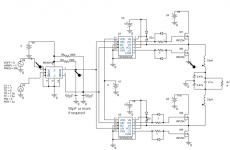
this is a small amp I'm trying to make. After a lot of efforts I finally have this circuit simulated. It's not finished yet, the overcurrent and start-up circuits have to be added(and maybe a feedback circuit). Problems now are quite a few such as the crossover distortion and the propagation time for the mosfet driver. Both high side and low side conduct at the same time for 70-80ns and current is about 80-100A(perfect for BBQ). The other problem about the mosfet driver is that the propagation time is almost 0.5usec.
Some questions:
1) volume control will be implemented by regulating source(24V) or input signal?
2) is there any way to make sure that the input signal will be between -1 and 1 Volts?
3) Any advice how to delay both low sides on drivers.
4) For all simulations the autoconverge is on(for orcad-spice) and the relults are not very accurate otherwise simulation can not be done.
Any thoughts or advices are welcome.
View attachment circuit.pdf
move the 1k resistors from th eMAX912 outputs to +5V, then add some caps from the max912 outputs to ground, this will get you some deadtime, around 56pF should do fine.
Like this:
Like this:
Attachments
Last edited:
Thanks for your quick response. But this will also add deadtime to high input of the drivers so high and low side mosfets will conduct at the same time again. isn't it?
I made it the way you told me and the only difference is that the output of MAX912 is now from 0.3V to (clearly) 5V(which was 4.7V). The output (1) of the comparator goes to the high side of the above driver and the low side of the other driver. So deadtime goes to both of them. Is this the correct way?
In the first picture it is the output of the comparator and in the second there is the current through the low side mosfet(watch the spikes.)


In the first picture it is the output of the comparator and in the second there is the current through the low side mosfet(watch the spikes.)
I have built this exact scheme or atleast a very similar one in the past, Mine was a single halfbridge output stage with split supplies. It ran off of 2x85VDC and with some 39-56pF caps as depicted here, the heatsink only got ever so slightly warm.
- Status
- Not open for further replies.
- Home
- Amplifiers
- Class D
- Advices- small amp(MAX912+HIP2500+IRFZ34)