Yeah don't say, I feel like trying to play Jenga on a skiff during thunderstrom 😉Trial and error "growing pains". 😱
Yep it's fixed already he is very helpful and fast indeed, I sometimes don't understand what he write because it gets esoteric, but that's true about you too😀It's awesome that you can get Kimmosto's excellent help here! 🙂
Hopefully it get's to a point where this thread is something that anyone can point to and say: "do it this way to get the proper result". 🙂
Well at least for me I really hope it does, if not it will encourage someone just to buy a pair of damn speakers instead 😀
Your files were okay. Few comments:
* "deg" is not needed in filenames. ARTA adds "deg", but it's not required by VituixCAD.
* "Hor" and "Ver" with capital is better to be "hor" and "ver" to be compatible with initial angle parsing settings in Options window.
* File size is huge. There is a setting for exporting txt/frd files with logaritmic frequency points (96 pts/oct) to reduce file size and increase reading speed. Time reference should be close to IR peak in order to use log f scale. This is already okay in your files.
Thanks Kimmo!
Work alright now
I have played with the file export to test the 96ppo, and it output a lot smaller size (21KB instead of 1200KB) but the import gets messed-up again and generate another error
I have tried with and without the 1/48 smoothing suggested by REW with same result.
If I click ok, I see the three files are set to 13° hor and when i try to change manually I get an error that it do not include a 13° hor

^What are response filenames and settings in 'Angle parsing from filename' group in Options window? Those should match though user can change interpreted angles by modifying Hor and Ver columns in frequency response list.
..yeah, that pdf is written from a particular perspective that just didn't work here. 😱
Could you specify what is "here"? Is it this thread alone or REW users generally or any thread where you play master specialist or diyaudio generally or some abstract user group used to play with some ancient poor methods for beginners and hard times with methods I prefer and recommend?
I'm aware that it's a bit technical and some understanding about measurements and data processing and speaker technology would be helpful. Many beginners have succeeded with it, but I'm sorry if it's too complex for you.
I'm guessing you have a reason (multi-axis sequencing?) for preferring the .pir export and utilizing VituixCAD's "Export" of frd files as in that particular pdf of yours..
Why to guess anything? Just ask.
ARTA has both off-axis measurement and export sequences (since 1.9.0). CLIO has off-axis measurement sequence (since forever) and REW has not been recommended partner with VCAD until V5.20 beta 7 28th March 2019 with new file naming system and reference time handling. Therefore measurement and data processing instructions are for ARTA.
^What are response filenames and settings in 'Angle parsing from filename' group in Options window? Those should match though user can change interpreted angles by modifying Hor and Ver columns in frequency response list.
Ok I understand, the filename was "hor_0_1m_13 June.txt"
Once I removed the 13 June from it it generated the issue on the "1" from "1m"
Then I remove all numbers but the 0, 30, 60 and it work ok, I'll pay attention to that in the future
I suppose the program read the file from the back and the first it find it assume it's the degrees, so it's like the Japanese Kanji 😀
I suppose the program read the file from the back and the first it find it assume it's the degrees, so it's like the Japanese Kanji 😀
You can specify in Options window whether angle value is searched from the end or from the beginning of filename. Initial setting (after program installation) is 'From end'. Both ARTA and CLIO use that search order. Files in common directory are sorted by driver name which is only logical i.e. the best option by far. Not any Japanese Kanji.
So you have selected wrong option in REW. You should select naming with root filename + consecutive numbering = off-axis angle. Not date & time which was only (and bad) naming system in REW before 5.20 beta 7.
Anyway, I'm not surprised that file naming is too difficult. 99% of technical support needs is caused by this simple thing, though file naming instructions are written in several places in documentation. Instructions are not read and followed by default until everyone has lost few hours for nothing.
Thanks for the tips Kimmo,
It's ok I now have registered that it's in that direction, not going to change, the kanji was just a joke but I'll avoid them in the future with you.
I don't see that option in naming convention option in REW where is it ?
Well I have read the instructions a few times, I'm unfortunately not able to remember every bit of it, but I can understand your apparent frustration
As you mention you did not recommended to use REW with your software before the recent changes, so I understand the help is not orientated yet to facilitate the instructions from users coming with REW.
I suppose most people with experience in speakers designs have invested in Clio or ARTA, so you get beginners like me that already have trouble understanding all the options that VituixCAD provide but also the specific language used in the associated guides
Nothing I can do to help you but try not to make the same mistake twice.
I don't see that option in naming convention option in REW where is it ?
Numbering option is "Add number" radio button. Setup window opens with small dialog icon/button on the right. There you can set next number and step e.g. 10.
Other settings essential for VCAD within red ellipses - assuming that measurement distance is 1000 mm (without extra delays e.g. due to dsp).
An externally hosted image should be here but it was not working when we last tested it.
Why to guess anything? Just ask.
-it was moot at that point (..I didn't care by then), you'd already said REW would be used with a frd/txt (merged) file range.
It just caused me confusion when Zoltan was asking and looking at your pdf. I was just providing context for my earlier confusion.
-as far as asking (generally): Zoltan was asking me, and I said I wasn't the one to be asked. Basically passing it on to you like you did with me (asking for the REW change from JohnPM). 😉
I could elucidate the problems with the pdf in reference to this *thread, but it would just add more confusion: in other words its counter-productive and moot.
*note: I still think the pdf is good: its content within its context was good. 🙂
Last edited:
..I sometimes don't understand what he write because it gets esoteric, but that's true about you too 😀
Yup. 😛 😀
Really though, confusion can arise from almost anything - it's just something that needs to accepted with most communication, and then work-through it as you can. 🙂
...I can understand your apparent frustration
I've just finalized svg export of charts and schematic images. Programming took 3-4 weeks. Reward was single thanks and lots of self education and avoided UV radiation. Some hypersensitivity is typical reaction after big changes.
I suppose most people with experience in speakers designs have invested in Clio or ARTA
REW beta is okay now so I will consider dedicated version of "Measurement preparations.pdf" for it. Umik-1 and other single channel measurements (most common with REW users) will not be supported of course so I'm not certain that writing would be "rewarding enough".
Numbering option is "Add number" radio button. Setup window opens with small dialog icon/button on the right. There you can set next number and step e.g. 10.
Other settings essential for VCAD within red ellipses - assuming that measurement distance is 1000 mm (without extra delays e.g. due to dsp).
An externally hosted image should be here but it was not working when we last tested it.
Ho damn I didn't check the "make a measurement" windows because I was loading my saved measurements, thanks I will pay attention to that for my next set of measurement
I've just finalized svg export of charts and schematic images. Programming took 3-4 weeks. Reward was single thanks and lots of self education and avoided UV radiation. Some hypersensitivity is typical reaction after big changes.
REW beta is okay now so I will consider dedicated version of "Measurement preparations.pdf" for it. Umik-1 and other single channel measurements (most common with REW users) will not be supported of course so I'm not certain that writing would be "rewarding enough".
Well I have seen in different threads that some show a near adulation in their writings about your work for this software, it may not be specifically about that feature that you have been working hard to provide, I am certainly not a spoke person for anybody here but I can tell you that I myself value very much what you have done and will do in the future with VituixCAD, and also your availability in helping in the VituixCAD thread and me specifically here.
So if you see me pester and whine at something here related to VituixCAD, know that it's human nature and more at me for not getting what's in there due to a lack of knowledge and not a lack of appreciation on what you did.
I would gladly help you with the work on that REW procedure but I need to understand what I am doing first.
If you see at some point that doing that is not rewarding for you and it's becoming a burden just don't do it, concentrate on what you like to do.
..the work on that REW procedure...
Here is preliminary version which is not yet tested in practice (I don't have anything boxed to measure at the moment): VituixCAD_Measurement Preparations_REW.pdf
'Export all measurements..' is probably fastest right after each measurement sequence, though this has separate time window setting + exporting sections copied from ARTA version.
It's great! You produced that quiet fast, I have already learned more things by reading it, and to me it's very complete.
I never did try the impedance measurement of REW, I have seen the options and I am happy there is warnings about it, I will stick to DATS.
A few things & questions if you don't mind;
- It would be a good thing to include from the other documentation you have made that schematic with the capacitor and maybe a warning at step 3 of page 1
- Is there a specific reason or advantage that you set the the sample rate at 88.2 kHz or is it just because that is your interface actual sample rate ?
- For the recommendation of using a range of 5 to 45khz, is it because there are more information's than if you do 20 to 20khz, in case you have a very expensive microphone?
- And about cabinet diffraction, is there a reason to do that if all the measurements made are on the actual baffle and already including the result of diffraction on & off axis?
- Not much related to the actual document while I am at it, I have heard in the video you made that the diffraction simulation is generated with only the on axis response, is there any advantage to trace or measure off-axis from an infinite baffle then ? Wich information is relevant to the design?
I'll put that into practice as soon as I can.
^
1. Last time I have checked REW, it did not support actual full dual channel measurement mode which is capable to compensate both magnitude and phase responses with reference signal. So you cannot use passive or active HP filter for protection so that measured response would be automatically corrected.
Usually measurement programs (ARTA, justMLS) calculate measured response divided by reference response which also voids need of soundcard calibration assuming that channels are close to identical. A/B is mathematically simple so using reference channel only for time locking is a bit confusing. Maybe JohnPM could add full dual mode to REW in near future? Or sweep with 1st order high pass and automatic compensation of the result response (just like in SoundEasy).
2. Internal frequency range of VituixCAD is fixed 5...40000 Hz. It's advantageous that measurement program provides full range that VituixCAD would not have to extrapolate response within 5-20 Hz and 20000-40000 Hz. Extrapolation is just composed first aid which could cause trouble if measured response has hump or dip close to end of range.
3. See previous. Response produced by measurement program is probably more logical and problem free with possible errors due to mic.
4. Diffraction simulation is needed to convert near field responses at low frequencies to quasi full space axial response. Baffle response exported with Diffraction tool affects to all responses below transition frequency (usually <300-500 Hz) in Merger tool. Time windowed far field responses already include diffraction and directivity above transition frequency.
This item should be clearly visible in Merger tool where you load (and can see the effect of) Diffraction response to Low frequency part.
5. This is already discussed here. Measuring in infinite baffle is useless if manufacturers' measurement in half space are available and quite reliable within 500...4000 Hz i.e. range where you have some but small possibility to play with diffraction effects = cabinet shape and driver location. Off-axis responses should stay logical with axial response which means that small radiators in medium size baffle without long rounds is bad design by default, and only few individual responses can be fixed with diffraction occurences (while some others go worse).
Last edited:
1. I understand that the idea is to get the fullrange of the speaker response and phase and that it would be great to have in REW a feature like you described, but if you plug a tweeter and you send him a sweep from 5Hz don't you risk breaking it ?
2. That question was more about the sample rate than the sweep, but I have the answer for the point 3.
4. I thought that low frequencies (before that baffle step transition) where in full space and therefore not impacted by diffraction, so when wavelength are larger than baffle am I wrong?
5. Yeah sorry to insist, it's because I did want to make sure I understand well the differences, is 1" 90° round-over considered long? Do you plan to include bevels in VituixCAD diffraction?
Thanks Kimmo
Last edited:
Hi Scott,
How are you? Your feet recovering ?
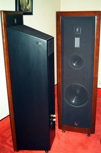
I just stumble upon that IRS Sigma baffles and the implantation with the dipole planar reminded me a bit of the design of the cabinets here :
Infinity Reference Standard Serie
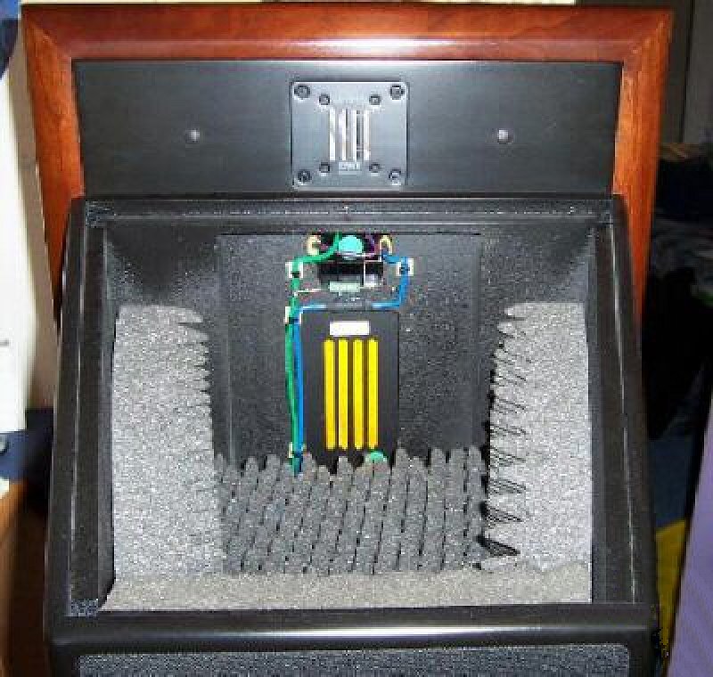
Also Is the the design of the front baffle that does not come flush with the back is something that work in general in regards to diffraction ? (I do not mean for the design now but more in general)
How are you? Your feet recovering ?
I just stumble upon that IRS Sigma baffles and the implantation with the dipole planar reminded me a bit of the design of the cabinets here :
Infinity Reference Standard Serie
Also Is the the design of the front baffle that does not come flush with the back is something that work in general in regards to diffraction ? (I do not mean for the design now but more in general)
Last edited:
1. Starting sweep much higher than 20 Hz could produce error curves first few octaves and forces simulator to extrapolation. High passed sweep + measurement compensation would avoid those, but lower S/N at low freq. produces errors anyway.
I don't usually protect domes and compression drivers with high pass or limiting sweep at LF. Fragile tweeters such as ribbons need some protection. Sweep for the others is 5-41000 Hz.
2. Sample rate and sweep range are close relatives because you cannot (usually sweep and) measure above sample rate / 2 so 88.2 kHz is the best available option.
4. Radiation to full space is not perfect above 0 Hz 🙂 Boxed speakers may have DI~3 dB at typical near2far transition frequency so directivity and diffraction effects exist on Low frequency part.
5. 1" round is short. No plans to include bevels. That would require different diffraction model than DED, and probably 2nd order diffraction calculation too. Probably some home made impulse response creation and then FFT.
- Home
- Design & Build
- Software Tools
- Advices on First Crossover Design (VituixCAD2)