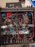
Hello everybody, I hope everybody is doing well. I recently purchased line stage 6sn7/300b based pre-amplifier. It uses toroidal power transformers as outputs transformers. The sound of the pramplifier as it was received was ok but not exceptional compared to the LTA pre I have been using. To see if the SQ improved I bypassed the input select rotatory switch, the balance potentiometer and replaced the remote controlled attenuator with a Goldpoint ladder attenuator, replaced the gain adjust potentiometer with a simple voltage divider circuit. The SQ has improved a good amount but not quite to the LTA pre level.
Can you advice on improving the output transformers? the ones installed are meant from converting 120/115 Volts 50/60 Hz to lower voltages for regulated power supplies. I am curious about kind of bandwidth of these transformers have when used in the audio frequency band. I guess I could buy the 2 models used and run a test...
The other potential improvement is to replace the coupling caps, installed are metallized propylene (MKP) in parallel with a paper in oil caps. All theses parts the potentiometers, selector switch, attenuattor and capacitors are common inexpensive parts.
I know the design is good and the preamp has the potential to get better SQ from it. Thank you in advance for your replies. I am interested on learning more about tube amps in general. Take care.
Trying to imagine what they were thinking, when designing it. Save money sounds like it. One would think you could plate load the big tube with a resistor or choke, cap couple off that into a voltage divider and have all the non ideal tranny stuff from non-audio transformers go away.Can you advice on improving the output transformers? the ones installed are meant from converting 120/115 Volts 50/60 Hz to lower voltages for regulated power supplies. I am curious about kind of bandwidth of these transformers have when used in the audio frequency band.
Which means they wanted it "in" for some reason. Sounds to me like someone whipped up a circuit, declared "sounds pretty good" despite what we're doing - let's go into production. Transformers do have an appreciable sound and it may be possible to have a "hit" with some rando tranny not intended for audio, but... I'd think you'd need actual audio trannys to get a better sound, or rid the circuit of that approach entirely.
I don’t. There is no need to use an output transformer in a preamp at all, let alone a repurposed power transformer.I know the design is good

Thanks for your input! I don't know much about valve circuits but I am learning. The amp sounds pleasant. I think I'll buy one and run tests.
Attachments
The transformers are fairly inexpensive, less than $30 each at one of the USA main electronic parts distributors.
Because I think it can be better. It has cheap components in the signal path like the transformers, I've already improve it, I can go further, but I'm ignorant on tube circuit designs.. I'm learning... Is good to hear the opinion of people who know more than me.
Given that the photo shows a complete rat's nest of components and you are dealing with high voltages here and there, I'd concentrate on making a circuit diagram first. That'll at least give you some steer as to whether replacing a component is going to make a trivial difference or perhaps have some genuine influence on the sound. No one here can give any sensible advice without seeing a circuit diagram first.
kind regards
Marek
kind regards
Marek
Thanks! I have a partial schematic now of the amplification section. The power supplies are in another box. It's a commercial product still in production, a designer/builder intellectual property so I'm not going to make it public.
Yes it looks messy that is the way point to point wiring looks like, I can imagine the amount of time it takes to build something like this, I can tell the audio path signal has been keep are short as possible and the wires that run long are twisted, a positive. Being PtoP it is easy for a DIY'er like me to make changes. I'm aware of the high voltage (I'm an electrical contractor, I have built SS amps in the past).
Thank you to everyone who had sent a reply. I will keep studying the amp and enjoying making improvements if possible.
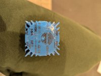
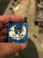
If you are referring to blue component in the photos it certainly looks like a mains transformer used in a power supply, 115/230V in and 15V - 0 - 15V out - most common use for this type of part is for a dual rail supply - very common in solid state gear. While it is possible one of these has been used in the signal path I can't see that being the case - I would be surprised if this component was any where near the signal path.
If it is part of a dual rail power supply then replacing it with a 'better' quality part will do nothing to the sound of the amp, the 2 blue parts pictured are not identical one outputs 15V - 0 - 15V and the other outputs 12V - 0 - 12V.
If it is part of a dual rail power supply then replacing it with a 'better' quality part will do nothing to the sound of the amp, the 2 blue parts pictured are not identical one outputs 15V - 0 - 15V and the other outputs 12V - 0 - 12V.
You cannot be serious?It's a commercial product still in production,
Publishing your own schematic of someone else’s preamp is not an IP violation.I have a partial schematic now of the amplification section. The power supplies are in another box. It's a commercial product still in production, a designer/builder intellectual property so I'm not going to make it public.
Post it.
I'm not kidding, it's still in production. If you want to purchase one you have to get on a waiting list.
The preamp uses a half of the 6sn7 as the first amplification stage, the output feeds the second half of the octal tube and the input of the DHT (300b or 45). The second amplification stages feed the preamplifier RCA outputs one coming from the DHT tube and the other coming out from the second half of the 6sn7. Both outputs go through caps before the transformers, the secondary of the transformers feed the RCA's outputs. The output of the DHT tube uses the transformer (dual in, dual out) to provide balanced outputs if desired by switching in/out a center tap since the secondaries are connected en series.
The design idea is that one gets two sound flavors: 6sn7 and DHT, one pair from the 6sn7, two pairs from the DHT. All of them can be used simultaneously.
Yes the transformers are in the audio signal path.
I would be really disappointed if I had paid full price for it, since it comes with basic quality tubes from the manufacturer. I bought it second hand from one of the main used hi-fi websites. Bypassing the cheap pots, attenuator, installing a regulated 12v power supply so I could use NOS 12sn7 tubes that I have and getting a pair of EML 45's have improved the sound quality.
Next is removing the transformers, figure out a way to load the plates and feed the RCA outputs. I don't care to much about the balanced outputs, balance and gain adjustments and volume remote control (I would consider a Khozmo input/volume control if I manage to get the SQ close to my LTA tube pre).
And what is a 300B doing in a preamp?
Unfortunately, that is a current fad. There are lots of imitation 300B tubes around, which have to be used for something.
Probably the output is parafeed: DHT loaded by CCS (DN2540), capacitor coupled to cheap (toroid PT) transformer.Next is removing the transformers, figure out a way to load the plates and feed the RCA outputs.
This is what point to point normally looks like, when done properly.

It's easier to understand, easier to document, easier to work on and you have so much more confidence that you won't electrocute yourself in the process than the amp you are contemplating altering. Strangely enough, when someone thinks things through to this level, the result is that it usually doesn't need anything doing to it until 30-50 years have gone by.
Make yourself a schematic and see whether you can make yours look more like this. The company that made this made 90,000 of them and they are still in business today. I'd hate to work on your amp and so will anyone else if you slip up, but good luck all the same. It's safe to say that everyone on this forum is a bit nervous on your behalf. Frankly, it just looks dangerous to me.
As for intellectual property, whoever made that amp has to argue in court that they have suffered a loss as a result, but I can't see anyone rushing to replicate their solderwork and take market share away from them.
kind regards
Marek
Personally, I'd walk away.
That rats nest in the photo should be the responsibility of the builder to fix. Nobody should ever consider paying someone their hard earned cash for that level of work. Sell it, and move on. By the time you fix it, it will be a completely different amplifier. You should start from scratch and build what you want, because in the end it will be cheaper and better than anything you could possibly do with this.
(The following is an attempt at comedy)
There should be a DiY audio, digital hall of shame, where the offenders are placed in shackles in the digital town square and the townsfolk are permitted to throw digital vegetables at them until they can recite retma color codes and promise to bundle wires in harnesses...
This is correct.Probably the output is parafeed: DHT loaded by CCS (DN2540), capacitor coupled to cheap (toroid PT) transformer.
Does Lundahl makes transformers that can replaceb the cheap PT? Since it is a line stage, gain is no necessary. I'm looking into this.
It's a DIY project now.
Thank you Marek you're kind. I'll follow your advice.This is what point to point normally looks like, when done properly.
View attachment 1426730
It's easier to understand, easier to document, easier to work on and you have so much more confidence that you won't electrocute yourself in the process than the amp you are contemplating altering. Strangely enough, when someone thinks things through to this level, the result is that it usually doesn't need anything doing to it until 30-50 years have gone by.
Make yourself a schematic and see whether you can make yours look more like this. The company that made this made 90,000 of them and they are still in business today. I'd hate to work on your amp and so will anyone else if you slip up, but good luck all the same. It's safe to say that everyone on this forum is a bit nervous on your behalf. Frankly, it just looks dangerous to me.
As for intellectual property, whoever made that amp has to argue in court that they have suffered a loss as a result, but I can't see anyone rushing to replicate their solderwork and take market share away from them.
kind regards
Marek
- Home
- Amplifiers
- Tubes / Valves
- advice upgrading output transformers and coupling caps in preamp