Hi, newbie here 🙂
I've got here a small homemade amp (not homemade by me, so no schematic available, though I have drawn a quick one out my self - attached) amp (two 12AX7's, one EL34) that I've been tasked with repairing. I know roughly what goes on in a tube head but it's not a very deep understanding...
I have been asked to repair it as it's recently lost a lot of volume. Different valves / cab checked out OK, and after testing inside I can see that the two first gain stages have a gain of 22 and 9, and the input stages saturate when the signal is about 30V - so far so good. There then seems to be some kind of buffer (i'm not familiar with this arrangement), which I'm assuming is working OK as I see about around 30V max on the grid (pin 5) of the EL34. The HT measures 366V.
I didn't perform the following measurements with the full 30V as the cathode resistor on the EL34 gets very hot and something buzzes.. but with 16.58V on the EL34 pin 5, there is 20.52V over the output transformer primary and 0.976V over the secondary, feeding an 8ohm load.
My first impression was that the problem was the output transformer as the output is a very low voltage, but when I worked out the reflected impedance from the information above I get 2857 ohms, which sounds OK from what I've gathered about the load impedance for a single EL34.
I don't want to spend the money on a new output transformer without being sure that it's definitely going to sort the problem! Could anyone point me in the right direction?
Attachments
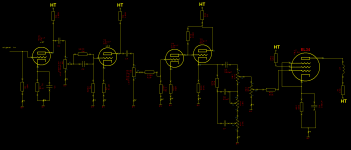
R25 (screen grid resistor) seems really high at 56k.
Was the amp ever working correctly? What's the input signal you are feeding it for your measurements? For guitar amps I usually use 20mV 1kHz. It seems like you are getting enough drive voltage to the EL34.
Probably should be a capacitor to ground after R24, something like 22uF-100uF, 450V.
Was the amp ever working correctly? What's the input signal you are feeding it for your measurements? For guitar amps I usually use 20mV 1kHz. It seems like you are getting enough drive voltage to the EL34.
Probably should be a capacitor to ground after R24, something like 22uF-100uF, 450V.
Last edited:
Hi, newbie here 🙂
I've got here a small homemade amp (not homemade by me, so no schematic available, though I have drawn a quick one out my self - attached) amp (two 12AX7's, one EL34) that I've been tasked with repairing. I know roughly what goes on in a tube head but it's not a very deep understanding...
I have been asked to repair it as it's recently lost a lot of volume. Different valves / cab checked out OK, and after testing inside I can see that the two first gain stages have a gain of 22 and 9, and the input stages saturate when the signal is about 30V - so far so good. There then seems to be some kind of buffer (i'm not familiar with this arrangement), which I'm assuming is working OK as I see about around 30V max on the grid (pin 5) of the EL34. The HT measures 366V.
I didn't perform the following measurements with the full 30V as the cathode resistor on the EL34 gets very hot and something buzzes.. but with 16.58V on the EL34 pin 5, there is 20.52V over the output transformer primary and 0.976V over the secondary, feeding an 8ohm load.
My first impression was that the problem was the output transformer as the output is a very low voltage, but when I worked out the reflected impedance from the information above I get 2857 ohms, which sounds OK from what I've gathered about the load impedance for a single EL34.
I don't want to spend the money on a new output transformer without being sure that it's definitely going to sort the problem! Could anyone point me in the right direction?
If you are 16.5 volts positive on pin 5 of the el34 and you are referencing ground,your .22uf cap or your .05 cap coming off the cathode of the driver would be leaking. Remove the El34 and test the dc voltage from pin 5 to ground and it should be very close to 0 vdc....With the EL34 installed,you need to measure DC from the cathode which is pin 8 of the EL34 as your reference and your pos lead on pin 5 and it should read minus 30vdc if pin 8 to ground is 30vdc.
R25 (screen grid resistor) seems really high at 56k.
Was the amp ever working correctly? What's the input signal you are feeding it for your measurements? For guitar amps I usually use 20mV 1kHz. It seems like you are getting enough drive voltage to the EL34.
Probably should be a capacitor to ground after R24, something like 22uF-100uF, 450V.
Hi, my bad - that resistor is 5.6K not 56K. The amp was working fine up until recently. After R24 is connected to the HT, on which there are the filter caps, I didn't include them on the schematic but there are 4 x 47uF. I am using a 500mV signal, in order to see the saturation of the input stage
If you are 16.5 volts positive on pin 5 of the el34 and you are referencing ground,your .22uf cap or your .05 cap coming off the cathode of the driver would be leaking. Remove the El34 and test the dc voltage from pin 5 to ground and it should be very close to 0 vdc....With the EL34 installed,you need to measure DC from the cathode which is pin 8 of the EL34 as your reference and your pos lead on pin 5 and it should read minus 30vdc if pin 8 to ground is 30vdc.
again, my bad - I meant AC not DC. I checked these and all is in order, grid is 1 or 2mV and measures -23V referenced to the cathode.
Is there another way to check the output transformer? Although it checks out reflected impedance wise, 16.58 ratio seems too much - I won't even get 1 watt out of it running full power with that!
If you have 20,52Vac on the primary and 0,976Vac on the secondary into an 8ohm load, that reflects 3k5, which is OK for a SE EL34.
However, with 16,58Vac on g1, you should have a lot more ac on the anode.
What dc is on the cathode?
Do you have access to a scope to see what is going on? Any signs of oscillation?
However, with 16,58Vac on g1, you should have a lot more ac on the anode.
What dc is on the cathode?
Do you have access to a scope to see what is going on? Any signs of oscillation?
hi Parafeed, that's interesting - my cathode is at 23.48V DC and no signs of oscillation...
If your cathode 23.48v then your cathode to grid would be minus 23.48 or close to it.
If you want to test the output trafo,you do that with a variac and your meter which to ACv. Make a plug to come out of your variac and take the EL34 out and unplug the amp.Set your variac at 0Vac and hook one of the ac leads to pin 3 of the EL34 socket and the other one to chassis ground. Put your AC meter on the 8ohm tap to ground and turn the variac on and turn it up until you get 1.0vac out or 2vac out. If that passes,your transformer is good but with either of those measurements you can calculate the impedance if you want.
Say your using the 1vac measurement. You then measure the output voltage of the variac to what it took to get that to 1vac out...Lets hypothetically say its 20vac. We then use the formula
Vin divided by voltage out squared times the output impedance
that would be 20 divided by 1 =20 and you square the 20 giving your 400 times 8 ohms would be 3200 ohms or 3.2k
Remember,this is a hypothetical measurement..You have to measure your own.
I think I see the issue with your amp..Being this is using two 12ax7s, I believe this is an integrated amp..Do this..Take 22uf or 33uf and bypass R15 which would be the 820 to ground..You only need like 35v or so and let us know what happens.
OK, so I have tested the output transfomer with a variac and it measures fine - about 50V on the primary gives two volts on the secondary.
Bypassing resistor R15 with a 33uF cap seems not to make any difference to the performance of the amplifier.
One thing I have noticed, is that if I drive a large signal into the power stage, the HT dips (from about 338V DC to 298V for a 70V signal) is this normal?
Also, something that Parafeed813 said earlierr interested me - what voltage should I see on the plate? For example if there is a 20V AC signal on the grid, will there just be a 20V signal on the plate? I had assumed that this stage was just unity gain like in a transistor amp - is that assumption incorrect?
OK, so I have tested the output transfomer with a variac and it measures fine - about 50V on the primary gives two volts on the secondary.
Bypassing resistor R15 with a 33uF cap seems not to make any difference to the performance of the amplifier.
One thing I have noticed, is that if I drive a large signal into the power stage, the HT dips (from about 338V DC to 298V for a 70V signal) is this normal?
Also, something that Parafeed813 said earlierr interested me - what voltage should I see on the plate? For example if there is a 20V AC signal on the grid, will there just be a 20V signal on the plate? I had assumed that this stage was just unity gain like in a transistor amp - is that assumption incorrect?
Incorrect. With this amp architecture, every stage has gain except the cathode follower. Reading AC signal from input to output (input, c1, C4, c5, el34 plate), you should see an increase in signal amplitude. At full volume, I would expect to see at least 150 volts peak to peak at the plate of the el34. Assuming none of the preamp stages are being severely overdriven, the signal should look pretty much the same shape on an o-scope.
If all the above is correct, and the el34 is in fact presenting a large signal to the output transformer, there isn't much else that can be going wrong. Either there is a bad connection somewhere, your impedance matching resistor on the opt primary has seriously changed value, the speaker isn't the right impedance, or the opt cannot do its job correctly.
aha! OK then. I just posted again about this - sorry in advance for any confusion...
I don't get any gain from the power stage! The signal on the plate is only slightly higher than on the grid (with 9.71V AC in I get 12.41V AC on the plate). What might be the reason for this? I have tried changing the EL34 and it makes no difference and all the neighboring components measure up fine! Any ideas what I could check next?
Cathode bypass cap?
I am guessing. But if the cathode bypass cap was open it would lower your gain and any increase in current would go through the resistor. You shouldn't see any ac signal at the cathode. If you do then the cap isn't working.
I am guessing. But if the cathode bypass cap was open it would lower your gain and any increase in current would go through the resistor. You shouldn't see any ac signal at the cathode. If you do then the cap isn't working.
I am guessing. But if the cathode bypass cap was open it would lower your gain and any increase in current would go through the resistor. You shouldn't see any ac signal at the cathode. If you do then the cap isn't working.
Thanks CapnDenny - cap measures fine and there is only about 40mV AC at the cathode.
What was the dc voltage at the plate of the power amp tube?
I wonder if you could replace the transformer with a resistor to test the tube circuit.
You can calculate the bias current from the voltage across the cathode resistor. Is that a correct value for this tube?
I wonder if you could replace the transformer with a resistor to test the tube circuit.
You can calculate the bias current from the voltage across the cathode resistor. Is that a correct value for this tube?
Can you double check that the screen resistor on the EL34 really is 5.6k. If it was 56k by mistake, that could explain the low gain.
It sounds to me like you have good signal coming into the power stage. With 16 vdc on your cathode, that's a little cold for a guitar amp, but not for hifi. The power stage should be putting a hurt on your ears with a 20 volt peak to peak signal on the el34 grid. You mentioned 70 volts when describing input signal, which caused power supply sag. At 70 volts ac anything (rms, peak, p-p), that el34 would be slamming square waves and ignition pulses into the opt. The speaker would be making loud, unpleasant noises.
Looking back at your original post, I see a resistor between the hot leg of the opt and ht source. This resistor is absent in nearly all guitar amps. Assuming the thing worked before with it in, It's probably ok.
Looking back at your original post, I see a resistor between the hot leg of the opt and ht source. This resistor is absent in nearly all guitar amps. Assuming the thing worked before with it in, It's probably ok.
If you really really really really want to confirm your opt is bad, load test it. Take it loose, rig the primary to your variac, and connect the secondary to your choice of load (i prefer anything labeled "blue thunder" or "bazooka"). Measure your output power: with USA power, the thing will only push thru a watt or three. This is loud enough to see, smell, or hear if the opt is ok or not. If if and only if...try it with 220 for high power mode. If this frightens you, rig a lamp in series with the primary.
- Status
- Not open for further replies.
- Home
- Live Sound
- Instruments and Amps
- advice troubleshooting?