With vintage gear, you have to know your intent and go about it a bit at a time.
If you want to restore it to like-new and keep the amp's original character- change out the electro's and adjust the bias. If the NFB electrolytics are shorted, DC offset will increase by several mV. Cost to try? $0.64
If you want to "improve" the amp's sound, that can go from a few part changes... to basically redesigning a bunch of the circuitry. You have to decide what you want to do.
I note the factory bias current spec seems low at 18.2mA (4mV/0R22), and if bias was set improperly (with an 8ohm load connected) the result would be close to Class B. Even worse with an +88mV DC offset, moving that by 11mA.
So the amp probably idles quite cool and sounds a bit thin? Check the bias too.
Prai,
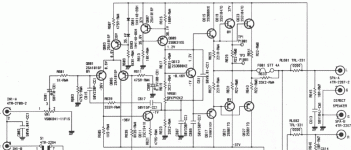
do you know if the output stage is EF or CFP?
That makes a difference to the required output bias current.
do you know if the output stage is EF or CFP?
That makes a difference to the required output bias current.
Rotel bias
This is always mystifying with ROTEL designs since their ancient Quasi designs in the RA- X10 series. Now, they are all simple EF, no CM,
VAS+CS, and here, 2 complementary output pairs. The link from the first post has the schematic download site - lots there too!
FWIW, My RA1060 is biased to only 7mV/0R22 (spec) it doesn't sound weak or thin but other amps like an ancient 150W Denon can,
at up to 3 times that bias current per pair. It comes good, SQ wise, at somewhere above 20mV/0R22
Not all we may agree correct here, stands up to commercial reality. 😕
My ancient RA820 (which I modded to use HEXFET outputs) is a very similar circuit to this one. I remember at the time that it was the budget amp to own and was often partnered and demo'd with quite exotic gear.
There is a fellow here now on forum from Oxford who had something to do with that (I think) UK model RA 820. Nigel may even recall the details.
Sheesh!
Does this mean I have a stinking-pile-of-stuff amp, by design?!?!? I had thought Rotel's were supposed to be half decent.
From what I had understood from AudioKarma, such an offset indicates audible distortion and isn't far off being bad for the speakers. They didn't mention amps designed with DC offset more-or-less built in. I have tested a bunch of amplifiers and most of them have been between 1mv (a 10 year old cheap sony mini) and 25mv (a 'hifi' sony).
The (generalised) rule on audioKarma was : up to 15mv DC offset: just fine, 15-30mv marginal, 30-50mv: not desirable, 50+: something's wrong.
That link is of my amp's little brother and almost confirming your statement, was at 88mv on both channels, and sounded bad. Replacing the transistors, caps and a resistor got it down to 30mv.
None of my Rotels are this high. 35 is more typical. The 9x series are great little amps. Not esoteric, but great for their market position. Better than the new ones and better than many for several times the price IMHO. I have 5 of various models. But they are getting old. Electrolytics do dry out and leak. Unfortunately, any electronic device over about 10 years old is past it's expected life span. Not having an adjustment may be considered a good design as there is no such thing as a good pot.
This means you have two choices. Recap starting at the main power supply caps, or put it to rest and be happy it had a good run. Of course, you have the possibility of selecting different caps in a few select locations if you want to move into the "mod" club.
I see the alternative Thielle Network on the output.
Is the R+C across the speaker terminals, or on the PCB?
Is the R+C across the speaker terminals, or on the PCB?
Andrew,
By "alternative", this looks to me like a conventional zobel. What do you see as not SOP? In all of my Rotels, it is on the PWB. (We don't call them PCB's any more. It freaks out firemen who rush into your factory and see PCB marked on boxes that are on fire. I know. I worked in that factory when it happened.)
I might increase C681 and 685 to 50uF, NPE to lower LF distortion. 617, 687 and 689 quality matters. Do not change value. A higher voltage rating electrolytic may mean marginally better DF. Check the catalogs.
Thiele network 2
The Zobel part usually sits on the board to get as close as practicable to the
source of whatever HF it's there for.
The coil follows this anywhere up to the output terminals even. Placing the Zobel
after the coil, as in the alternative, would seem to stifle that idea but my understanding
is that it utilises the coil damping resistor as a part of the Zobel R and this puts a
different complexion on the whole network. Most applications I've seen seem to miss
the point entirely, so why did they bother?
It means putting the coil right in trouble to implement it optimally but after the
fuse here isn't great anyway.
Neville Thiele did the original work and both circuits work.
Look at his original paper.
Dr Cherry did a paper showing that Thiele's original two variations were the extremes out at the limits of a continuous range of Output Networks. All of which can do the job of providing a load at most frequencies that the amp needs to see to aid stability.
I have previously posted an xls of the Cherry calculations which also shows the two limiting Thiele variations.
Thanks for all the advice, folks. Very interesting reading. Has made my indecision as to what to do all them ore acute. 🙂
So what load should be connected if not 8ohms as the service manual says? What wattage of resistor should I be using for that?
Should I put the bias up a bit? what would you suggest as a safe measurement?
With vintage gear, you have to know your intent and go about it a bit at a time.
If you want to restore it to like-new and keep the amp's original character- change out the electro's and adjust the bias. If the NFB electrolytics are shorted, DC offset will increase by several mV. Cost to try? $0.64
If you want to "improve" the amp's sound, that can go from a few part changes... to basically redesigning a bunch of the circuitry. You have to decide what you want to do.
I note the factory bias current spec seems low at 18.2mA (4mV/0R22), and if bias was set improperly (with an 8ohm load connected) the result would be close to Class B. Even worse with an +88mV DC offset, moving that by 11mA.
So the amp probably idles quite cool and sounds a bit thin? Check the bias too.
So what load should be connected if not 8ohms as the service manual says? What wattage of resistor should I be using for that?
Should I put the bias up a bit? what would you suggest as a safe measurement?
The service manual lost something in translation. The 8 ohm load is to warm up the amp for 5 minutes ("with rated output"), then bias current is adjusted/measured with no-load/no signal on the amp, to eliminate errors due to DC offset.
Since the bias current is quite low on this amp, the 88mV output DC offset is a problem. With a speaker connected, that's 11.1mA extra, so one transistor/pair is at 18mA and the other at 23.7mA (theoretically). I'm not sure how this imbalance affects crossover distortion. Setting bias current will also confirm if the amp needs some repairs, if the DC offset gets worse.
I calculate the amp will dissipate (heat) at idle:
4mV 18.2mA 5.4W/channel (factory)
5mV 22.3mA 6.7W/channel
6mV 27.3mA 8.0W/channel
7mV 31.8mA 9.4W/channel
8mV 36.4mA 10.8W/channel
If you up the bias current, the limit is the amp running hot/or thermal run away if the temperature compensation is a lousy design. Many DIY designs are running 50-100mA bias.
I'm guessing your bias-trimpots are old and oxidised, so they may need cleaning. I just mark their position and rotate them back and forth a few times to clean them up. Schematic shows they default to minimum bias current if the wiper opens.
The service manual lost something in translation. The 8 ohm load is to warm up the amp for 5 minutes ("with rated output"), then bias current is adjusted/measured with no-load/no signal on the amp, to eliminate errors due to DC offset.
Since the bias current is quite low on this amp, the 88mV output DC offset is a problem. With a speaker connected, that's 11.1mA extra, so one transistor/pair is at 18mA and the other at 23.7mA (theoretically). I'm not sure how this imbalance affects crossover distortion. Setting bias current will also confirm if the amp needs some repairs, if the DC offset gets worse.
I calculate the amp will dissipate (heat) at idle:
4mV 18.2mA 5.4W/channel (factory)
5mV 22.3mA 6.7W/channel
6mV 27.3mA 8.0W/channel
7mV 31.8mA 9.4W/channel
8mV 36.4mA 10.8W/channel
If you up the bias current, the limit is the amp running hot/or thermal run away if the temperature compensation is a lousy design. Many DIY designs are running 50-100mA bias.
I'm guessing your bias-trimpots are old and oxidised, so they may need cleaning. I just mark their position and rotate them back and forth a few times to clean them up. Schematic shows they default to minimum bias current if the wiper opens.
Ok, thanks for that. I would certainly have kept the resistor there. So the 8ohm resistor needs to be able to take more than 10W max, in theory?
No, you are misunderstanding the post.
Those powers 5.4W to 10.8W are the heat being sent to the heatsink.
The load resistor is there to allow you to heat up the amplifier by driving power into the rated load.
You will need a pair of resistor (one to each channel) and each rated to exceed the maximum power output of the amplifier. Probably better to aim for >=100W resistors.
- Status
- Not open for further replies.
- Home
- Amplifiers
- Solid State
- Advice on replacing transistors in a Rotel