...include 12dB of NFB...
How do you figure 12dB gain reduction?
I figure 5W in 16r is 10Vrms, the EL84 needs 9V peak or 7Vrms to do that, the triode has gain like 50, input needs 0.14Vrms. 12dB up would be 0.56V. 10V out and 0.5V in makes 20:1. If the lower leg is 100r, the leg from the output should be near 2K. Not 20K, which seems to be "no NFB".
Or experiment. Put a 50K pot in for NFB. FIRST howl-test!! The OT gives a 50:50 chance of being wrong phase. On the build-bench it is wrong more often than not. While a 5W amp may not burst a speaker it sure will wake the neighbors. If not howling right away, reduce the pot value until tone gets softer (or louder to howl). By your arbitrary 12dB, you want 1/4 gain. I can estimate 12dB (half-amplitude twice) by ear, though most people won't.
Anyway that 12dB was picked out of a pants-cuff. It's not wrong, but there is no reason to bet it is optimum.
BTW: the EL84 at 285V 33mA should be loaded in 8K-10K, not 5K. 285 Vpk, and assumed 30mA actual plate current, is 8.5K. (I think your triode load should have been nearer 10K than 5K.)
How do you figure 12dB gain reduction?
I figure 5W in 16r is 10Vrms, the EL84 needs 9V peak or 7Vrms to do that, the triode has gain like 50, input needs 0.14Vrms. 12dB up would be 0.56V. 10V out and 0.5V in makes 20:1. If the lower leg is 100r, the leg from the output should be near 2K. Not 20K, which seems to be "no NFB".
My apologies, what I've done there is post the wrong circuit 😱.
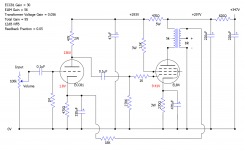
This is the circuit I'd made my calculations from, with a lower leg of 470r:

I'm getting my method from Merlin's book, 'Designing Valve Preamps for Guitar', which is naturally guitar specific, but the math presumably translates?
If I'm following him, first I calculate the individual gains:
- ECC81 = 47.1
- EL84 = 56.5
- Transformer = 0.056
then multiply them together:
47.1x56.5x0.056 = 149
For 12dB NFB, I calculate a feedback factor of 3.98, which translates to a feedback fraction of 0.02 (3.98-1/149 = 0.02).
Next I calculated the total resistance (R) of the lower arm, which is rk (47+11/61 = 1k) in parallel with Rk (470r). R = 320k.
Finally, Merlin gives the formula for calculating Rf, (R/B-R). 320/0.02-320 = 15680 ohms. I rounded up to 18k as it's the closest value I have to hand.
The choice of 12dB was reasonably arbitrary, although Merlin suggests an increase in bandwidth of 1 octave for each 6dB of NFB. 2 octaves seemed like as good a starting point as any.
I'll take your advice, and use a 50k pot to adjust it on the bench.
Thanks,
Matt.
BTW: the EL84 at 285V 33mA should be loaded in 8K-10K, not 5K. 285 Vpk, and assumed 30mA actual plate current, is 8.5K. (I think your triode load should have been nearer 10K than 5K.)
Ironically, I designed the circuit for a 10k load, but was advised earlier in the thread to lower it to 5k. I'll re-do my calculations for a 10k load, the practice will do me good 🙂.
Last edited:
Member
Joined 2009
Paid Member
Interesting project. I also had a similar project, but without any driver tube. And I also found that in Pentode mode it is too strident.
One thing I eneded up doing was to implement some plate to screen feedback but using a frequency selective network - I made feedback for treble frequencies. This means cleaning up the treble.
Yukon Gold - a spud amp
One thing I eneded up doing was to implement some plate to screen feedback but using a frequency selective network - I made feedback for treble frequencies. This means cleaning up the treble.
Yukon Gold - a spud amp
The 470 Ohm resistor has a 330uF cap across it; there is no feedback at all, the 330uf shorts it to ground.
Try a 100 Ohm resistor to ground, in series with a 390 Ohm resistor to the cathode; and put the 330uF across the 390 Ohm resistor. Then connect the feedback resistor to the junction of the 100 Ohm and 390 Ohm resistors.
As was earlier stated in this thread, the 18k Ohm does not apply any practical feedback.
You need the 18k Ohm resistor to be much lower, but not as low as would be the case for triode wired output.
I realise this is an old thread but wondered was an ECC82 used with the Plate to Plate 100K Rfb resistor instead of the ECC81 ?
Thanks
Thanks
Hi, I have decided on a 6J5 input tube 18K CFB - SE / EL84 Pentode CCS on the cathode , 22V Zener Diode to the control grid of the EL84
ECC81 a little bright sounding for me .
ECC81 a little bright sounding for me .