Howdy
Before I lay out the PCB, I'd appreciate some feedback on my schematic for a preamp PSU (attached).
It's based almost entirely on Rod Elliot's version, with a few minor tweaks:
My toroid is 15-0-15, at 50VA. Overkill, I know.
This PSU will be driving a number of modules within the preamp - a microcontroller, input selection relays, digital volume control, encoder, LCD as well as buffering the outputs. There is also a fairly beefy headphone amplifier (OPA2134 and two BUF634s).
Anything I should add/remove/tweak or otherwise be aware of?
Thanks!
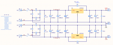
Before I lay out the PCB, I'd appreciate some feedback on my schematic for a preamp PSU (attached).
It's based almost entirely on Rod Elliot's version, with a few minor tweaks:
- Added a 2.2K bleed resistor to each rail
- Added a 1000uF cap to each rail
- Using full bridge rectifier layout (8 diodes)
My toroid is 15-0-15, at 50VA. Overkill, I know.
This PSU will be driving a number of modules within the preamp - a microcontroller, input selection relays, digital volume control, encoder, LCD as well as buffering the outputs. There is also a fairly beefy headphone amplifier (OPA2134 and two BUF634s).
Anything I should add/remove/tweak or otherwise be aware of?
Thanks!
Attachments
I would recommend to power all the control circuits from a different PSU.
1uF cap that you added does not add much to the performance of the PSU but will take up some space on the PCB. I would just remove it.
Since you implemented full bridge rectifiers for each rail you have a potential issue if one fuse blows you lose a rail which typically results in half to full rail DC voltage at the output of your pre-amp unless it is AC coupled. Using center tap configuration you do not have such problem even if one fuse blows you will have increased voltage sag under load and increased ripple but both rails will be present.
Regards,
Oleg
in my comment above should read "1mF cap..."... 1uF cap that you added...
Realized that after reading DF96's post... 🙂
In principle looks good and should work fine.
Maybe the added 1000uF caps don´t change behaviour much (if at all), but that does not change my statement above.
Being a *Preamp* , I wouldn´t worry too much about a fuse blowing, not impossible but SO unlikely under such light duty 🙂
Maybe the added 1000uF caps don´t change behaviour much (if at all), but that does not change my statement above.
Being a *Preamp* , I wouldn´t worry too much about a fuse blowing, not impossible but SO unlikely under such light duty 🙂

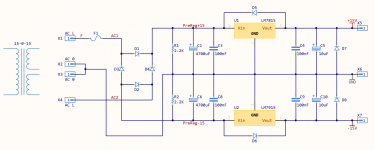
There we go - single bridge rectifier, cut down on the smoothing caps.
As for using a different power supply for the digital components, would it be optimal to use a separate transformer entirely, or could I simply use a 15-0-15V transformer with an additional 6V winding? (This would then be regulated down to 5V).
Thanks!
As for using a different power supply for the digital components, would it be optimal to use a separate transformer entirely, or could I simply use a 15-0-15V transformer with an additional 6V winding? (This would then be regulated down to 5V).
Thanks!
Attachments
I would recommend a totally separate PSU for control circuits including extra transformer. Ideally I would put small transformer and +5V reg on a single PCB.
I would recommend a totally separate PSU for control circuits including extra transformer. Ideally I would put small transformer and +5V reg on a single PCB.
Okay, awesome, will do. I'll use one of those all-in-one 5V RECOM or BLOCK transformers to do the heavy (or light) lifting, with a couple of 100uF + 1uF caps on the output to smooth over any ripples.
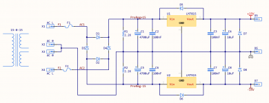
Put a snubbers from each transformer output to center tap - this will help mitigate diode switching noise
Increase your transformer voltage and put a C-R-C filter before each regulator - - this will make for a slightly quieter supply
Increase your transformer voltage and put a C-R-C filter before each regulator - - this will make for a slightly quieter supply
- Status
- Not open for further replies.
- Home
- Amplifiers
- Power Supplies
- Advice on Preamp PSU schematic