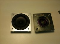
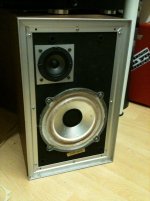
Not had chance to modify the crossovers yet but decided to mount the new tweeters properly first. I had a few different ideas but I ended up making adapter plates so as not to mess with the cabs. Made them up on the kitchen floor in a hurry but they look fine and do the job 🙂. Comedy hex-head bolts were all I had in the right size, at least they're the right colour 😉
Attachments

This is really VERY GOOD, Dan. Looks like a very nice choice for replacement. An internet first for sure. Lots of these old Wharfedale and LEAK speakers will need something like this. 😀
http://monacor.co.uk/products/speakerbuilding-hifi-4/vnr/101150/
I appreciate it's early days, and we don't know quite where to go on the crossover, but what are your listening impressions? Maybe just some level adjustment? 🙂
http://monacor.co.uk/products/speakerbuilding-hifi-4/vnr/101150/
I appreciate it's early days, and we don't know quite where to go on the crossover, but what are your listening impressions? Maybe just some level adjustment? 🙂
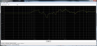
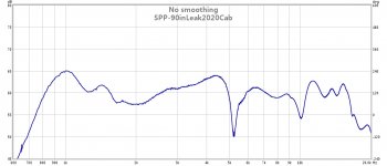
Sounds great - really close to original tweeter I think but with a bit more detail. In an attempt to be scientific I'm going to try measuring the frequency response of the driver/tweeters, obviously this isn't going to fantastically accurate but should be fun and help me to learn about crossovers 😉. Attached is a quick plot 2cm away from the new tweeter (with just the resistor added to the the crossover), will do some more testing when I get time 🙂
Thanks, Dan.
Thanks, Dan.
Attachments
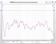
Had another quick go at measuring the speakers and found a great bit of software called FEW. This time I measured one driver with the other disconnected. Looks like I don't need any resistance on the crossover for the tweeter 🙂. Also, not sure what is going on at 5KHz and 10Khz?
Attachments

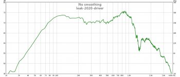
Very interesting. Can't quite say where those suckouts are coming from, but you gotta wonder if the non-polar capacitors are well past their sell-by date.
Alcap 50V Low Loss Electrolytic capacitors for all audio and hi-fi loudspeaker crossover applications
They don't build them to last.
Alcap 50V Low Loss Electrolytic capacitors for all audio and hi-fi loudspeaker crossover applications
They don't build them to last.
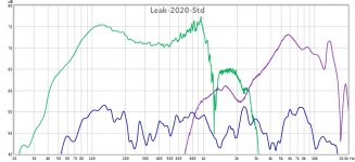
I just ordered some of those caps you suggested (ended up getting them from Cricklewood as delivery was a bit cheaper and they had a load of other little bits I needed to stock up on 🙂). Did some more quick measurements on the standard speaker, each driver individually 2cm away from centre, and both connected about a foot away for interest (with a bit of smoothing on the last one). Not seeing those two steep troughs with the old driver, will do some more tests with new caps and resistors off the crossover (though not too many, seeing such massively uneven responses is getting depressing!).
Cheers, Dan.
Cheers, Dan.
Attachments
I used to go to Henry's on Cricklewood Broadway back in the day. It always looked like jumble sale inside! 😀
You've gotta be careful running crossovers without drivers. It presents an almost short circuit to the amp at certain frequencies. It's more SOP to replace a driver with an 8 ohm wirewound when measuring stuff like transfer function.
I wonder if shunting a 15 ohm resistor across the tweeter might help damp out some resonance here. It's all quite metallic around the tweeter, and might be physically ringing.
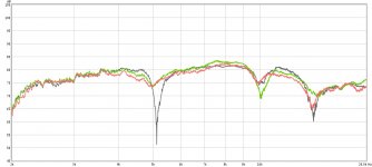
I put the new caps on the crossovers and this didn't seems to make a difference, I tried some resistors across the tweeter and this seems to help. In the piccy no resistance is in grey, 22 ohms is green and 10 ohms is red. 15 as you originally suggested looks like it would be optimum. I'll get some wirewounds ordered, will 5 Watts be enough?
Also, do you think my rather quick n dirty method of mounting the tweeters could be causing the lumpy response? With a bit of minor woodwork it would be possible to mount them flush if this would help.
Have stopped testing them with drivers disconnected - thanks for the tip!!
Cheers, Dan.
Also, do you think my rather quick n dirty method of mounting the tweeters could be causing the lumpy response? With a bit of minor woodwork it would be possible to mount them flush if this would help.
Have stopped testing them with drivers disconnected - thanks for the tip!!
Cheers, Dan.
Attachments
Some resistance (say 2-3 ohm 3-7W wirewound) at the input to the tweeter filter, along with the 15 ohm (10W wirewound) shunt would raise the treble impedance nicely to nearer 8 ohms, albeit reduce treble level. Cheap as chips, wirewound resistors. I have a good stock.
Most of the modelling I did put the tweeter out of phase with the woofer, but that is guesswork and depends how deep the woofer is. Worth trying and measuring though.
It might also damp out some physical ringing to put the tweeter behind the homemade mounting plates. You get to use the cardboard damping on the front of the tweeter that way.
Truthfully I'd trust my ears more than measurements here. Very interesting project, you are working hard at it. 🙂
Very nice job Flibble, while my 2020's are currently languishing in my attic sanctuary for abused speakers, along with a couple of pairs of Kef Crestas which system7 helped enormously with, they did sound very nice , especially the bass. If you have managed to find a tweeter that improves on the somewhat gritty nature of the original, they could be worth revisiting. I think their styling is probably quite fashionable once again.
Ah, Mr. Jives! Master fixer! Good to see you around...😀
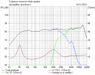
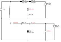
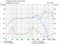
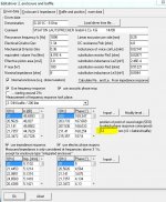
Dan, I was looking at that crossover again to see what you are up against. It's actually all a bit ugly. I really don't like that 3rd order bass. People don't use that circuit these days because phase is usually ghastly. I prefer a single 1.5mH coil and about 6-10uF and maybe a 3.3 ohm resistor, but it's quite hard to model without knowing the woofer inductance. There is often a tendency for bass filters to have a nasty peak near crossover that needs a resistor on the shunt.
The tweeter filter is also a bit of a shocker. The impedance goes very low around 3 ohms at a point, but it doesn't rolloff much. Adding a 15 ohm tweeter shunt makes it worse too. Awkward amplifier load. Exact modelling depends on the driver efficiencies, so ignore the frequency response in the first sim.
It seems to me that the first fix is to add some input resistance at the tweeter filter to get the impedance up. I also found a third order tweeter filter MUCH better aligned. The resistor on the bass shunt damps a peak.
As an initial plan, I would suggest that the tweeter filter really needs that input resistor (2-6 ohms...) along with the 15 ohm W/W shunt you've already fitted. You'll have to judge exact value to get the tweeter level right. As you can see, there might be some further mods later. Sorry, long post.
Attachments
Steve - really appreciate the info, I will have to order in/scrounge some more bits but I'll try out the crossover setup you suggest. I'm not precious about keeping the crossover layout authentic if bigger changes might get better results 🙂. I was running them with 10ohms wedged across both tweeters (have the new tweeters in both cabs now), ended up ripping them off as it seemed to be attenuating the treble too much. The holes in the adapter plates are too messy to mount the tweeters behind them, will see if I can make up some better ones in work next week 😉
jives11 - I'm pretty pleased with the sound (as you say - bass is their forte 🙂) and the new tweeters are defo an improvement over originals 😀. Starting over I'd be tempted by the Monacor HT-22/8 which you can buy for less than a fiver each, response doesn't look quite as flat as the ones I went for - and the silver dust caps are very 70s 😉 - but they should mount neatly without any adapter plates etc.
Cheers, Dan.
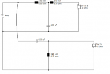
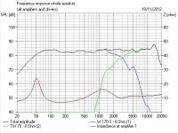
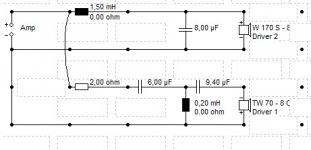
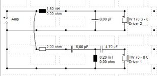
I wondered if a simpler bass filter might work better here. This one lets through a bit more cone breakup, but as with old complex 4th order Celestion bass crossovers, I think simpler is better and I wondered why they even did it.
Bear in mind my modelling is kinda guessing. But then old speakers were often not too scientific either.
It's simple enough to try. You just short out the second 0.5mH coil. Sleep on it. 🙂
Bear in mind my modelling is kinda guessing. But then old speakers were often not too scientific either.
It's simple enough to try. You just short out the second 0.5mH coil. Sleep on it. 🙂
Attachments

So far I've hooked up both crossovers outside of the cabs so I can play with them more easily 🙂. Using something similar to that last crossover schematic and they're sounding excellent. I ended up mounting the tweeters on the back of the adapter plates, and those troughs at 5 and 10khs were due to my test setup (standing wave I'm assuming with mic very close to tweeter cone). Will post some pics soon 🙂
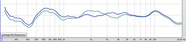
I did some more playing and realised that the tweeter appeared to be out of phase (had noticed that the speakers sounded funny and saw a big troughs around the crossover region), sorted that and did some more trial and error tests and attached is the best I could get it looking at the SPL response. Just knocked up the crossover in boxsim and added in the cabinet measurements - is all new to me but the SPL looks to be a similar shape to what I measured 🙂. Now wondering if I'm going to be able to improve on it? I'm pretty happy with the way they're sounding 😀
Attachments
![Boxsim V1.20 - VISATON-Edition [CUsersDanDesktopProjektesim1.BPJ] 28112012 211825.bmp.jpg](/community/data/attachments/297/297346-5e1aea9181eba5f5e757e0896b102eb6.jpg?hash=XhrqkYHrpf)
Last edited:
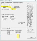
This is all guesswork, but I can tell you are interested in what's going on. Getting phase right is a bit of a pig without accurate modelling, but the idea is that phase lines up around crossover to give good imaging.
This is for a 3kHz crossover using a standard dome tweeter with a VERY nice bass notch at 5kHz which cuts down some cone breakup rubbish from the bass and does wonderful things to line up phase. To see where the bass notch acts, just short the shunt resistor on the bass.
What makes it hard for you is that you really don't know quite where the acoustic centres of the drivers are. You can adjust these in Boxsim to simulate your drivers. I really don't know if the TW 70 paper cone is a very good approximation to your polycone tweeter. For that matter I don't know a lot about leak sandwich drivers either. But trust your ears here. Hope that helps a bit. Not my most coherent post. 😀
An externally hosted image should be here but it was not working when we last tested it.
This is for a 3kHz crossover using a standard dome tweeter with a VERY nice bass notch at 5kHz which cuts down some cone breakup rubbish from the bass and does wonderful things to line up phase. To see where the bass notch acts, just short the shunt resistor on the bass.
An externally hosted image should be here but it was not working when we last tested it.
An externally hosted image should be here but it was not working when we last tested it.
What makes it hard for you is that you really don't know quite where the acoustic centres of the drivers are. You can adjust these in Boxsim to simulate your drivers. I really don't know if the TW 70 paper cone is a very good approximation to your polycone tweeter. For that matter I don't know a lot about leak sandwich drivers either. But trust your ears here. Hope that helps a bit. Not my most coherent post. 😀
Attachments
Last edited:
Thanks for the info Steve - really appreciate it. Managed to get hold of a copy of the Loudspeaker Design Cookbook (a real paper copy not a knocked off pdf 😉) so I can do some homework 🙂. I'll call the Leak's finished for the moment, they sound really good to me and I'm sure there is still room for improvement but, like you say, with out being able to sim them it's hard to make proper progress. Now I just need an excuse to build up some new speakers with drivers I can model 😛
I guess this post has kinda turned into a blog so I'll just keep going 😉 Couldn't resit having one last play, after fiddling around a bit I got the following which is the flattest I've seen the response from them yet - blue plot is with the 0.5mh shorted green is without, I decided to leave it shorted to keep it flatter through the middle. Now it might actually be time to stop playing with them 🙂 need to find some of the 2020's big brothers with the 12" sandwich drivers to see what they sound like....
Cheers, Dan.
Cheers, Dan.
Attachments
Last edited:
- Status
- Not open for further replies.
- Home
- Loudspeakers
- Multi-Way
- Advice on Leak 2020 Speakers