Hello. im a newcomer to this site and i'm hoping to get some advice 🙂
As a first audio orientated project i'm working on a hybrid Headphone amp. It is mostly pretty simple. A 6N16B-V tube in Class-A mode operating at a voltage of aprox 85v is to amplify the input signal of which the output is then decoupled to a solid-state stage consisting of a OPA2134 and TPA6120a2 in a composite setup.
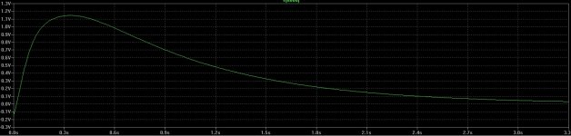
My problem is that early tests and simulations show that during startup the decoupling capacitor between the tube and solid-state stage will get a bit of a inrush resulting in a sizable offset (~2v for 3 seconds) to the solid-stage and thus also to the final output. I need advice on how to best deal with this as the last thing i want is to send 2v dc into headphones when turning the device on.
Right now i'm thinking of either using a additional buffer between the tube and composite with it's own output decoupling capacitor (having that deal with initial offset rather then output-stage). Another one would be Output capacitor at the end to protect the headphone (tough that would cost a bit of space), but yeah input from experienced people would be very much appreciated.
Speaking about Output capacitors. If i were to use that as a solution and my solid-state stage is dual-rail powered with a nominal DC-offset of nearly 0v (give or take a few mV). would i need to use a bi-polar? or would a well-rated polar cap work fine aswell?
As a first audio orientated project i'm working on a hybrid Headphone amp. It is mostly pretty simple. A 6N16B-V tube in Class-A mode operating at a voltage of aprox 85v is to amplify the input signal of which the output is then decoupled to a solid-state stage consisting of a OPA2134 and TPA6120a2 in a composite setup.
My problem is that early tests and simulations show that during startup the decoupling capacitor between the tube and solid-state stage will get a bit of a inrush resulting in a sizable offset (~2v for 3 seconds) to the solid-stage and thus also to the final output. I need advice on how to best deal with this as the last thing i want is to send 2v dc into headphones when turning the device on.
Right now i'm thinking of either using a additional buffer between the tube and composite with it's own output decoupling capacitor (having that deal with initial offset rather then output-stage). Another one would be Output capacitor at the end to protect the headphone (tough that would cost a bit of space), but yeah input from experienced people would be very much appreciated.
Speaking about Output capacitors. If i were to use that as a solution and my solid-state stage is dual-rail powered with a nominal DC-offset of nearly 0v (give or take a few mV). would i need to use a bi-polar? or would a well-rated polar cap work fine aswell?
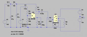
during startup the decoupling capacitor between the tube and solid-state stage
will get a bit of a inrush resulting in a sizable offset (~2v for 3 seconds)
Can you post the schematic? You can certainly reduce the tube circuit's output capacitor
value to reduce the pulse. It's likely to be sized too large anyway, if the pulse is that long.
Can you post the schematic? You can certainly reduce the tube circuit's output capacitor
value to reduce the pulse. It's likely to be sized too large anyway, if the pulse is that long.
I don't got a finalized schematic yet. but ive added my current test-bench. that is what i have right now for testing and the simulation result of the output of the decoupling capacitor. im using ltspice for simulating.
Reducing the decoupling capacitor further is something i hope to avoid as that would put the cutoff point above the 10hz and still leaves me with a initial peak of nearly a volt for the first 1-2seconds.
Attachments
Last edited:
Valves settle down when warm.
I know that and the circuit settles after a short while, but i need advice in keeping everything from sending a potentially headphone killing pulse (assuming that a 2 second lasting pulse of 1v can kill) into my headphones when turned on and everything is slowly settling. :<
i want to improve the safety of my amp and need advice on what ways to minimize it.
I've built a couple tube hybrid amplifiers. They had a microcontroller protection system that would start the tube heater circuit first, thirty seconds later it would start the main supply, then about 15 seconds later,it would start monitoring for DC offset on the output. If all was good it would engage the speaker relay. This could easily be connected to a headphone amp.
Reducing the decoupling capacitor further is something i hope to avoid
as that would put the cutoff point above the 10hz.
As a check, delete the U1 circuit and just connect R4 to ground.
Do you still get the same transient after C3? If so, is the duration the same?
If so, then a simple fix is to use a NC relay to short the output of C3 to ground
until the warmup time is over, with the relay being energized after that.
For turn-off, the timing capacitor would have to be shorted to ground via a diode
that is connected to a positive DC voltage that collapses quickly, like the filament's
DC supply input capacitor. Of course, the main output could be shorted to ground instead,
if there is a resistor in series with the output.
Last edited:
Yes, as jwilhelm just mentioned - I would never use a DC-coupled circuit with my speakers or headphones without a proper power-on delay and DC offset protection. It will simply connect your headphones when the circuit is settled and disconnect them immediately in case of trouble.
Simulation is one thing, reality can often be quite different. The circuit in post #3 will kill the opamp at switch on because R1 and C3 couple the opamp directly to the 140 volt rail. That will put a high voltage transient on the opamp input... zap ! It could well do the same at power off too as the opamp input pin gets pulled to far negative.
You need two small fast signal clamp diodes on the opamp - input to clamp the voltage at that point to no higher than V3 + 0.6v and V4 - 0.6v.
Getting a truly silent switch on/off can only be done with a series switch element (relay or solid state) to the headphones. You could use a relay to short the output to ground for a few seconds but that would only work if you were prepared to add a few ohms of series resistance to the output so that the feedback network around the opamp was still functional.
As a check, delete the U1 circuit and just connect R4 to ground.
Do you still get the same transient after C3? If so, is the duration the same?
If so, then a simple fix is to use a NC relay to short the output of C3 to ground
until the warmup time is over, with the relay being energized after that.
For turn-off, the timing capacitor would have to be shorted to ground via a diode
that is connected to a positive DC voltage that collapses quickly, like the filament's
DC supply input capacitor. Of course, the main output could be shorted to ground instead,
if there is a resistor in series with the output.
Everything stays the same. The reason it lasts so long is cause the inrush is originating from the RC-chain filtering the supply to the tube. that one is taking time to fill up and the capacitor seems to be following that curve (a slow start-up can still be seen as a signal i suppose! ^^😉
A relay on the capacitor sounds like a simple idea i could easilly integrate. Those solid-state relays aren't really big nor expensive nowadays. would just need to figure out how to keep it conducting for about half a minute. would need a very small footprint timer...or use a timer capacitor as you suggest (in which case could you point me to a resource on how to determine that?)
I've built a couple tube hybrid amplifiers. They had a microcontroller protection system that would start the tube heater circuit first, thirty seconds later it would start the main supply, then about 15 seconds later,it would start monitoring for DC offset on the output. If all was good it would engage the speaker relay. This could easily be connected to a headphone amp.
Hmmm. do you have any examples of this? I don't know how i would have a microcontroller measure the DC-offset. Probably not something i want to do right now, but definitly worth learning about for other amps!
Simulation is one thing, reality can often be quite different. The circuit in post #3 will kill the opamp at switch on because R1 and C3 couple the opamp directly to the 140 volt rail. That will put a high voltage transient on the opamp input... zap ! It could well do the same at power off too as the opamp input pin gets pulled to far negative.
You need two small fast signal clamp diodes on the opamp - input to clamp the voltage at that point to no higher than V3 + 0.6v and V4 - 0.6v.
Getting a truly silent switch on/off can only be done with a series switch element (relay or solid state) to the headphones. You could use a relay to short the output to ground for a few seconds but that would only work if you were prepared to add a few ohms of series resistance to the output so that the feedback network around the opamp was still functional.
Relays seem to be pretty popular here. a relay on the output is doable. the 6120a2 gets a bit unstable anyway if there isn't a minimal impedance. Also using diodes to protect the input from exceeding the common-mode. didn't think of that.
Ok so i got to look into the use of Relays, Diodes to protect the input from exceeding common-mode limitations and the possible use of a microcontroller to monitor DC-offset. Right now im leaning for Rayma's solution of shorting the capacitor output to reference during startup. this would solve the problem of keeping the start up transient from reaching the solid-state stage and seems to be a solution that wouldn't take up a lot of boardspace (im kind of trying to fit everything within the Cadsoft eagle freeware 10*8cm limitation).
Nobody answered my question tough about the if i were to opt to try to protect the headphone through a sizable output capacitor (still considering even if it's "just in case"). would a bi-polar be a must or can a polar be used since the dc-bias would be zero??
Last edited:
A polarised cap to protect the headphone output would only work if the fault condition was of the 'correct' polarity. Large bipolars could be hard to source... easy option is two polarised in series - to -.
My thoughts... as the valve stage is AC coupled, why not simplify the whole thing and have the opamp running on a single rail. That way you can safely use a large polarised cap and have no worries over offset faults. Use a simple relay configured to short the phones out for a few seconds at power on, and arranged so it drops out again very quickly at power off. No complications, just a dead simple single transistor arrangement and a suitable auxiliary rail with a 'low' time constant that collapses quickly.
My thoughts... as the valve stage is AC coupled, why not simplify the whole thing and have the opamp running on a single rail. That way you can safely use a large polarised cap and have no worries over offset faults. Use a simple relay configured to short the phones out for a few seconds at power on, and arranged so it drops out again very quickly at power off. No complications, just a dead simple single transistor arrangement and a suitable auxiliary rail with a 'low' time constant that collapses quickly.
Vzaichenko's tube hybrid amplifiers are actually what brought about the 21'st Century Protection system. http://www.diyaudio.com/forums/soli...-st-century-protection-board.html#post4110406 I've evolved the design enough now that it can be compacted into a headphone amp chassis. The microcontroller tells the speaker relay when to turn on. The speaker relay module monitors the amplifier output for DC, and shuts itself down if it detects any, while at the same time signaling the microcontroller, which in turn shuts the amplifier down before it damages itself too badly.
A polarised cap to protect the headphone output would only work if the fault condition was of the 'correct' polarity. Large bipolars could be hard to source... easy option is two polarised in series - to -.
My thoughts... as the valve stage is AC coupled, why not simplify the whole thing and have the opamp running on a single rail. That way you can safely use a large polarised cap and have no worries over offset faults. Use a simple relay configured to short the phones out for a few seconds at power on, and arranged so it drops out again very quickly at power off. No complications, just a dead simple single transistor arrangement and a suitable auxiliary rail with a 'low' time constant that collapses quickly.
I suppose i could do that. The amp rails are generated through a isolated DC/DC converter module so i should be able to run it as a single-supply with minimal effort (if i decide to use a cap anyway). A set of relays should also be easy to implement. Just need to figure out which ones to get.
Thanks to everyone for the input. Has given quite a bit of stuff to take a look at and experiment with! 😀
use a timer capacitor, could you point me to a resource would a bi-polar be a must
or can a polar be used since the dc-bias would be zero??
There are simple LM555 timer circuits that can drive a small relay.
Examples: Project 104 - Preamp/ crossover muting circuit or Muring Relay PCB
If you decide to go this route, also I can email you a 12V circuit that I've used that has worked reliably.
You want a bipolar cap for the output, since the load is ground referenced,
and there are bipolar supplies for the op amp.
Ok. here is where i am right now:
The power-supply is originating from a 12v DC wall-wart (2A) and all rails will be generated through DC-DC converters (boost for HV,Step-down for heater, isolated dual-rail connected as non-isolating for the Amps).
I am going to use a pair of output capacitors regardless. I'll be using a pair of Nichicon ES (the green bipolar audio caps) 470uf (that would bring cutoff to a few herz at most with 250ohm phones). Ive grown fond of nichicon as a source of decent capacitors.
Altough the transient will be pretty harmless due to the rather slow-start of the tube-stage (the RC chain acts as a soft-start so the transient peak remains well within the common-mode limitation) i will still be looking into the use of Solid-state relays to switch the output and/or short the tube signal decoupling capacitor to ground at startup. Should note tough that i'm trying to keep everything as small as possible on a single circuit board with at most a few small vertically attached modules.
If you or anyone else has a simple small-footprint power-on delay/fast shutdown circuit. Please do point me in the right direction 🙂
I am aware that my project isn't exactly taking the most optimal route or going for perfection by a long-shot. It is just a first-time project where i try multiple things as a learning experience in regards of designing simple tube amps,Working within certain restrictions, Battling distortion, getting the right voltages and so on. with the bonus that if it sounds well enough i have a small hybrid amp to listen through in the end. 🙂
Any relays would only need be small outline signal types and with as high a coil resistance (for minimum power dissipation) as possible.
Really simple would be:
1. Half wave rectifier and 'small' reservoir cap.
2. A single NPN or FET across the supply with a relay in the collector/drain circuit.
3. A simple C/R delay on the base/gate together with a diode to discharge the timing cap when the rail collapses.
The FET is easy to work with and a preferred option imo.
Any relays would only need be small outline signal types and with as high a coil resistance (for minimum power dissipation) as possible.
Really simple would be:
1. Half wave rectifier and 'small' reservoir cap.
2. A single NPN or FET across the supply with a relay in the collector/drain circuit.
3. A simple C/R delay on the base/gate together with a diode to discharge the timing cap when the rail collapses.
The FET is easy to work with and a preferred option imo.
Any pointers on Solid-state relays? I don't think i can fit in a mechanical relay with the space i have left right now so im taking a look at SSRs as they can be very small. so far ive been able to see i know that i would have to be carefull about the on-resistance and that the Relay is designed for AC and not DC operation.
Pick a couple mosfets with low on resistance and a SS relay driver IC and build your own. I use IPB025N10N3 G mosfets and ASSR-V622-302E drivers, but if you want to save board space there are lots of more compact options. You won't need 180A current handling either.
Attachments
Last edited:
Pick a couple mosfets with low on resistance and a SS relay driver IC and build your own. I use IPB025N10N3 G mosfets and ASSR-V622-302E drivers, but if you want to save board space there are lots of more compact options. You won't need 180A current handling either.
Building my own relay... sounds like a fun miniature project to do!
Again to everyone: thanks for all the input. something tells me i will be learning quite a bit here! 😉
- Status
- Not open for further replies.
- Home
- Amplifiers
- Solid State
- Advice needed on dealing with startup output offset