Hello!
Mostly hang out over in the tube section here, but I've got a project based around tubes worst enemy, a low impedance "high" wattage load 😄
Got gifted a fairly nice 4ohm full range speaker element for a mono BT speaker project I've been toying with. The BT receiver has a D-class amp rated at 3W based around the PAM8303 chip. It sounds fairly good, but it's just not nearly enough power.
I haven't designed a solid state amplifier for audio before so I'm looking for some general topology and component advice. Not looking to build someone else's design but inspiration is always appreciated 🙂
Since no-one has responded, I recommend starting with Nelson Pass's AB100. https://www.diyaudio.com/community/threads/ab100-class-ab-power-amplifier.227503
This is a very conventional circuit topology that can easily be scaled to lower power.
Ed
This is a very conventional circuit topology that can easily be scaled to lower power.
Ed

Thank you, I saw your message just as I powered on my first prototype though 😅Since no-one has responded, I recommend starting with Nelson Pass's AB100. https://www.diyaudio.com/community/threads/ab100-class-ab-power-amplifier.227503
This is a very conventional circuit topology that can easily be scaled to lower power.
Ed
Buuut it didn't work right when soldered together so I think that will still be useful 🙂
Right now it's just a very simple diode bias push-pull with the first matched BJTs I found laying around, they are BDX33/34(Darlingtons). Not sure if they are optimal but I belive they should work?
I should have at least 3v amplitude out of the BT receiver so I think I can skip the drive parts. Haven't look at it through engineering goggles yet though, really just threw a handful of parts together and I got signal out when in a breadboard, didn't work right when soldered together though 😒
Just a darlington buffer isn’t likely to be useful. It will “work” if all you have is a line-out, but if you already a have a little amp capable of driving a speaker it will not be any louder than what you already have. You need voltage gain. Also, the darlingtons would need a decent amount of quiescent current not to sound scratchy with no feedback at all. Doing that with just diode bias requires too much fiddling - the kind where you could make a mistake and fry something. With a vbe multiplier for bias you know to just start with the pot at maximum resistance and just turn it until either it “sounds decent” or measures correctly - it won’t be nearly as touchy and doesn’t require soldering in various low-ohm resistors by experiment. If the buffer (as designed, with diode bias) is put in the feedback loop of a general purpose op amp (say, a 5532) it will do what you’re probably expecting here. It’s also a very good first project because the chance of success is high.
Use an op amp rated for +/-22V supplies and the power supply of the KM41 works perfectly. It might be a smidge too high a voltage for op amps that are only happy to +/-16 or 18 volts. All it might take is one little surge from an appliance kicking in on the opposite phase, and poof. Effing around with regulators adds complexity and increases the chances something will go wrong. Don’t want to build a power supply at all? A +/- 15 or 18 volt 4 amp switcher, or pair of singles wired together works. You could get away with less current capacity depending on how long it takes for over current protection to kick in since the average draw is MUCH less. But use one for the full 4 amps and it’s guaranteed not to misbehave - and would still be cheap.
Use an op amp rated for +/-22V supplies and the power supply of the KM41 works perfectly. It might be a smidge too high a voltage for op amps that are only happy to +/-16 or 18 volts. All it might take is one little surge from an appliance kicking in on the opposite phase, and poof. Effing around with regulators adds complexity and increases the chances something will go wrong. Don’t want to build a power supply at all? A +/- 15 or 18 volt 4 amp switcher, or pair of singles wired together works. You could get away with less current capacity depending on how long it takes for over current protection to kick in since the average draw is MUCH less. But use one for the full 4 amps and it’s guaranteed not to misbehave - and would still be cheap.
twenty five watt retro amp with speaker cap for no speaker burn: https://www.diyaudio.com/community/threads/retro-amp-50w-single-supply.236256/page-31 post # 606 . From apex
6 transistors.
6 transistors.
I have no qualms building a PSU, might be able to dig up a switcher though to save some effort. I'm. Surprised at how basic the PSU is in that drawing though, no RC filter or anything? Just transformer and then reservoir caps 🤔Just a darlington buffer isn’t likely to be useful. It will “work” if all you have is a line-out, but if you already a have a little amp capable of driving a speaker it will not be any louder than what you already have. You need voltage gain. Also, the darlingtons would need a decent amount of quiescent current not to sound scratchy with no feedback at all. Doing that with just diode bias requires too much fiddling - the kind where you could make a mistake and fry something. With a vbe multiplier for bias you know to just start with the pot at maximum resistance and just turn it until either it “sounds decent” or measures correctly - it won’t be nearly as touchy and doesn’t require soldering in various low-ohm resistors by experiment. If the buffer (as designed, with diode bias) is put in the feedback loop of a general purpose op amp (say, a 5532) it will do what you’re probably expecting here. It’s also a very good first project because the chance of success is high.
Use an op amp rated for +/-22V supplies and the power supply of the KM41 works perfectly. It might be a smidge too high a voltage for op amps that are only happy to +/-16 or 18 volts. All it might take is one little surge from an appliance kicking in on the opposite phase, and poof. Effing around with regulators adds complexity and increases the chances something will go wrong. Don’t want to build a power supply at all? A +/- 15 or 18 volt 4 amp switcher, or pair of singles wired together works. You could get away with less current capacity depending on how long it takes for over current protection to kick in since the average draw is MUCH less. But use one for the full 4 amps and it’s guaranteed not to misbehave - and would still be cheap.
You make a good point though, I do need voltage gain stage too. (well, the BUX33/34 power stage didn't want to work outside of the breadboard either so I need an entire amp still 😂)
Not sure I've got any OPs that will take +/-22V around though.
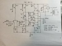
Maybe I should just build the KM-41, should have everything needed laying around. Found a few of the TIP41/42 and I've got loads of BCwhatevers in TO-92 packages laying around. Seems like a lot of transistors though? Also no output cap? I'll probably add one if I follow that schematic
Oh no! What if my 0.1¢ transistor explodes! What a disaster! 😱the kind where you could make a mistake and fry something
That's really nice and simple, I like it! Don't have the those specific BC transistors though so I'd need to swap them for something elsetwenty five watt retro amp with speaker cap for no speaker burn: https://www.diyaudio.com/community/threads/retro-amp-50w-single-supply.236256/page-31 post # 606 . From apex
6 transistors.
I'd use MPSA56 input transistor, drivers & VAS MJE15028/29 , output transistors MJ15003 or MJ15015 (TO3) or MJW21194 or MJL3281 or MJL4281 (plastic) . All from On semi, readily available in USA. Don't forget the heatsink on the output transistors, and I use little heatsinks on the drivers & VAS for ultimate reliability. I have this operating in the 70 W version on 69 vdc, sound is great. 70 w version page 22 of retro thread http://www.diyaudio.com/forums/solid-state/236256-retro-amp-50w-single-supply-22.html , pictures of my point to point boardDon't have the those specific BC transistors though so I'd need to swap them for something else
These super simple amps perform better with a regulated power supply. I regulate my 74 supply with a zeneri diode stack of 72 v driving 5 parallel TIP147 darlington transistors, .33 ohm emitter resistors after each transistor, followed by another 3300 e-cap. 3300 cap drives 2 channels. of 70 w each. 2 channels of 10 w you could use onel TIP147 regulator and a 1000 uf cap.
Last edited:
Bipolar transistor amplifiers naturally have good rejection of supply ripple. Better supplies are needed for high-performance amplifiers.I have no qualms building a PSU, might be able to dig up a switcher though to save some effort. I'm. Surprised at how basic the PSU is in that drawing though, no RC filter or anything? Just transformer and then reservoir caps 🤔
Ed
Don't belive i have those input transistors on hand either but great options I'm sure. I'd prefer to use some of the hundreds of transistors that are already laying around in the lab though 🙂I'd use MPSA56 input transistor, drivers & VAS MJE15028/29 , output transistors MJ15003 or MJ15015 (TO3) or MJW21194 or MJL3281 or MJL4281 (plastic) . All from On semi, readily available in USA. Don't for get the heatsink on the output transistors, and I use little heatsinks on the drivers & VAS for ultimate reliability. I have this operating in the 70 W version on 69 vdc, sound is great. 70 w version page 22 of retro thread http://www.diyaudio.com/forums/solid-state/236256-retro-amp-50w-single-supply-22.html , pictures of my point to point board
I'll probably add a filter for my own sanity honestly 😂Bipolar transistor amplifiers naturally have good rejection of supply ripple. Better supplies are needed for high-performance amplifiers.
Ed
How much voltage are you going to run it off of? You don’t really need big/specialized/expensive transistors down on low power supply voltage. Regardless of which circuit design you use. It’s when you start cranking the voltage that you start needing TO-220 drivers and TO-3 outputs. Around 30-ish volts and TIPs and 2N3904’s can be used.
I tried TIP31c/32c as drivers in an AX6. They sounded like ****. MJE15028/29 replacements produced actual high frequencies. Read the Ft of each.Around 30-ish volts and TIPs and 2N3904’s can be used.
2n5320/5322 from RCA on the surviving PC15 board sounded fine from 1970. 2n5320/22 are 50 mhz ft. The blown side PC15 with lifted traces I replaced with AX6. Same NTE181 (same soa as MJ15003) output transistors both sides.
Last edited:
Not TIPs as drivers - but as outputs. For a 10 watt amp they work fine - any TIP 6 amps or more. Driven by 2N3904/6. Up on 70 volt supplies its pretty iffy, even if you select for voltage. But that’s bigger than any 10 watt amp.
I was thinking 25V or so.How much voltage are you going to run it off of? You don’t really need big/specialized/expensive transistors down on low power supply voltage. Regardless of which circuit design you use. It’s when you start cranking the voltage that you start needing TO-220 drivers and TO-3 outputs. Around 30-ish volts and TIPs and 2N3904’s can be used.
Finished putting together the retro 25W circuit on a breadboard, not getting any output and when the input voltage gets to about 15-20V the top 1N4148 explodes... All the transistors come out good on my tester though even after the 1N4148 has popped a couple of times so that's something at least.
Didn't have the listed transistors so I did the following substitutions:
BC560 -> BC557b
BC639 -> BC337
BC640 -> BC327
BD243 -> 2N6123
Most likely the issue is somewhere in the wiring but maybe it's in the choice of transistors, no clue. Will probably rebuild it tomorrow and see if it starts behaving 🙃
I'd expect some output but with a 1kHz 2Vrms test tone as input I get no output over my dummy 4ohm load. There is current draw until the diode pops so something is doing something at least.
I don’t know what would cause the diode to poof other than collector-base breakdown in the NPN driver. If that is happening around 15 or so volts I might suspect you’ve got collector and emitter reversed. It normally kills the transistor if there isn’t anything to limit the current.
Those BC### transistors have pinouts all over the map. The BC639 datasheet I have shows with the flat pointing at you ECB which is as weird as a cat's pajamas. BCE and EBC are more usual pinouts of TO92. Different brands may have different pinouts in TO92.
You could put a 22 ohm >2 watt resistor in for the fuse and slow down explosions until you can probe the circuit for improbable voltages. Us an alligator clip on the negative and I find I slip the probe less onto random points with a Pamona grabber instead of a inch long bare probe.
You could put a 22 ohm >2 watt resistor in for the fuse and slow down explosions until you can probe the circuit for improbable voltages. Us an alligator clip on the negative and I find I slip the probe less onto random points with a Pamona grabber instead of a inch long bare probe.
Good thing you pointed out the pinout... I just assumed they would all be BCE but the BC557b is CBE, so that's definitely wired wrong at the very least 🤦probably not BCE for the 300s either and that's likely why the 1N4148 is going poof 😅Those BC### transistors have pinouts all over the map. The BC639 datasheet I have shows with the flat pointing at you ECB which is as weird as a cat's pajamas. BCE and EBC are more usual pinouts of TO92. Different brands may have different pinouts in TO92.
You could put a 22 ohm >2 watt resistor in for the fuse and slow down explosions until you can probe the circuit for improbable voltages. Us an alligator clip on the negative and I find I slip the probe less onto random points with a Pamona grabber instead of a inch long bare probe.
Good things:
Fixed a lot of wiring errors as I rebuilt it from scratch
I now have output!
Can confirm the power is 25W into 4ohm when fed with 30V and 50W at 50V!
The output resembles the input most of the time!
The bad things:
The output is very square, at best symmetrically so but most often not.
The output frequency is unstable and goes all over the place when the voltage is touched
The amplitude of the input doesn't impact the amplitude of the output, only messes with the frequency again
Casualties:
Killed two 2N6123s
Turned the output cap into smoke as it was not the voltage rating
Melted part of the breadboard
I belive the feedback must be messed up somehow, if I pull the 1Mohm resistor that should remove the feedback right? Could also be that this is all still on a breadboard with jumpers all over the place too but I don't want to commit to making it properly before I know all the transistors I've picked are up for it
There is the Aksa Lender based Alpha 20 design by Aksa. It’s 20w Class A. There is a 4 ohm mod discussed in thread.


Here is link to 4ohm variant by Danny66:
https://www.diyaudio.com/community/...rid-aleph-alpha-amplifier.318102/post-5536066
Here is link to 4ohm variant by Danny66:
https://www.diyaudio.com/community/...rid-aleph-alpha-amplifier.318102/post-5536066
- Home
- Amplifiers
- Solid State
- Advice/inspiration for 10-20W into 4ohm amplifier