Going to try to make a ta2020 PCB. Have never tried this before so have mercy 😉. Would appreciate any advice for layout etc. so there's no major mistakes before the gerbers are sent to the fab house. Current state of schematic and layout in the attachement section.
Attachments
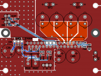
Changes in layout
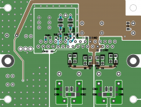
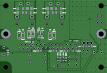
Error in schematic for the DC offset decoupling led to rework in layout. Board size is now 72.5x50mm.
Description:
*5V external voltage regulator
*DC offset circuit
*Ferrite bead linking analog and power ground
*SMD capacitor footprints designed for Rubycon MU or ST / Cornell FCA / Panasonic ECPU(A), Vishay PHP 1W SMD resistor at output filter, NXP PMEG4010ETR,115 clamping diodes.
Again any advice regarding layout/groundplane/component selection would be appreciated.
Attachments

- Status
- Not open for further replies.