Any of the Spud amps would fit a budget amp definition and be pretty simple to build. Last I checked the pricing of OPTs and such, my Novar Spud could be built for about $200 including power and output transformers. The Novar Spud provides 5 W, which is plenty to drive your speakers.
For more power, my DG300B is an option, though, it's decidedly not a budget amp. A typical build budget starts around $1k, including the chassis.
An EL34 PP amp would be a nice option as well, though, if you're aiming for lower power, I'd go with a single-ended design.
Tom
For more power, my DG300B is an option, though, it's decidedly not a budget amp. A typical build budget starts around $1k, including the chassis.
An EL34 PP amp would be a nice option as well, though, if you're aiming for lower power, I'd go with a single-ended design.
Tom
Last edited:
Member
Joined 2009
Paid Member
I like the 6as7 idea too - I have a SET based on this tube and its a really hansom looking tube when its glowing. But its not really that linear as a SET so one day I might try it in PP.
Baby Huey? I haven't built one, but it's been on my list of schematics to try for a long time. Just waiting until I stumble across the right iron.
http://www.diyaudio.com/forums/tubes-valves/72536-el84-amp-baby-huey.html
Tubelab SSE would do over 10W in Ultralinear mode. That's a board based design. Very easy to execute, flexible with the tubes and transformers. Lots of support on the forum, so it's good for beginners.
Tubelab | Dedicated to advancing the state of the art in affordable high end audio.
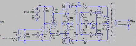
First, I have to admit this concept has actually not been build up to now, and sure needs a bit of polishing here and there.I hope that someone will ask you to show us that design.
The x-coupled inner feedback loop is part of the trick on how to equalize tube tolerances for stable performance.
It's not the simplest or cheapest effort, but should offer about 12~13W of clean and pure class A triode power.
Attachments
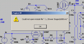
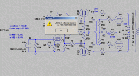
Need to remove all those folder directory and just use 6080.inc
Works fine.. It needs only 12Vpp on the driver stage. Looks like a good schematic to use op-amp phase splitter and save some heater power.
edit: it's not Class A by the way.. It yields 13W class AB1
Works fine.. It needs only 12Vpp on the driver stage. Looks like a good schematic to use op-amp phase splitter and save some heater power.
edit: it's not Class A by the way.. It yields 13W class AB1
Last edited:
It is. The power tubes don't cut off at any time during the cycle. It may look funny though b/c of strong non-linearity of the 6080 bottles..edit: it's not Class A by the way.. It yields 13W class AB1
Use the supplied tube .inc files. Remove the leading "..\.." from the .inc statements to use the tube models in the same directory as the .asc file.I can't get it working.
LT Spice don't identify 6080 even if the 6080.inc is in the same folder.
It is. The power tubes don't cut off at any time during the cycle. It may look funny though b/c of strong non-linearity of the 6080 bottles..
Each 6080 idles at around 50mA and yet draws peak current up to 150mA which is considerably more than twice the idle current. Last time i check, this falls to Class AB.. Anyway, i will cut the Class A or AB discussion here as i won't hijack the thread any further. Interesting design, by the way.. i might use the driver and output stage design. Thank you.
Let's say it depends on the definition of class A you're using.. Here's another one: the output tubes are idling at 2x12W, yet the audio output power at the onset of clipping is 13W, which by conventional wisdom is not possible in pure class A, and would indicate a (very shallow) class AB1.
Strange beasts those 6AS7x/6080ies..
Strange beasts those 6AS7x/6080ies..
You have plenty of options
Tikkis
If you can build an amp or have someone help you or do it for you,the EL-Cheapo is the best option due to its simplistic nature and its superb performance for very little money. It is also a fun project and you can tweak it to your heart's delight.The amp is very well designed,and several now use it as their main amp.
There are options as well. I'm very fond of the Leak Stereo 20 and those are commonly found in the 220v version but again,they need to be recapped if they haven't been done already.. The ELcheapo or ELcheapo Grande are two amps that are very popular and they create a sense of pride and understanding of the hobby as well.
Hello,
I built a pair of loudspeakers using Fostex FF165WK drivers (thanks for all who gave me advice). I housed the drivers in 18 ltr enclosures (space limitations) The result surprised me positively and I am greatly enjoying their sound.
My amplifier is a 60 watts / channel transistor amp. Because the speakers are very sensitive, I would like to try them with some tube amplifier. I should think that around 10 watts per channel would suffice nicely.
To cut to the chase, could anybody suggest some budget priced (500-1000 dollars) tube amplifier that would have a nice and balanced sound.
I live in Europe so the amp should be able to cope with 230 V power feed.
Thanking you all in advance.
Tikkis,
Helsinki, Finland
Tikkis
If you can build an amp or have someone help you or do it for you,the EL-Cheapo is the best option due to its simplistic nature and its superb performance for very little money. It is also a fun project and you can tweak it to your heart's delight.The amp is very well designed,and several now use it as their main amp.
There are options as well. I'm very fond of the Leak Stereo 20 and those are commonly found in the 220v version but again,they need to be recapped if they haven't been done already.. The ELcheapo or ELcheapo Grande are two amps that are very popular and they create a sense of pride and understanding of the hobby as well.
First, I have to admit this concept has actually not been build up to now, and sure needs a bit of polishing here and there.
The x-coupled inner feedback loop is part of the trick on how to equalize tube tolerances for stable performance.
It's not the simplest or cheapest effort, but should offer about 12~13W of clean and pure class A triode power.
Hi, I've been messing around with Williamson driver circuits, so I have a question about yours.
I noticed that R12 and R13 are only 12k ohms each. Isn't that a very heavy load on the 6SN7's? I figure 6SN7 in a differential driver has ra of about 8k to 10k. Those 12k anode load resistors are not even twice the valve's ra. Won't distortion be very high in this stage?
Thanks for any insight into this you can offer.
--
...I have a design in my drawer which yields lower distortion with fewer parts and 100V less Ub...
The linearity of your output stage is "done" with common cathode resistor R5 (270 ohms).
This subject was discussed here in january:
http://www.diyaudio.com/forums/tubes-valves/284812-please-explain-h3-3rd-harmonic-cancellation.html
This sort of feedback is effective, but only in very limited load impedance range.
This can clearly be seen when your circuit is simulated with different load resistances.
As a reference the THD is only 0,14 % with 11 W to 8 ohms, but the performance collapses with 4 ohms.
With only 6,5 W to 4 ohms, the THD is some 16 times bigger, i.e. 2,2 %.
With 6 W to 16 ohms it is better (0,56%), but the increase of the THD is conciderable.
In january when the original thread appeared I tested the effect of this cathode feedback in my 6N13S PP amplifier.
I noticed that very little improvement to the overall linearity can be achieved with the common cathode resistor, and the optimum size of the cathode resistor may not be (with 6AS7G etc.) bigger than some 30...40 ohms.
If the common cathode resistor were optimized to 8 ohms, the linearity with 4 and 16 ohms load was worse than without the resistor and vice versa.
...I noticed that R12 and R13 are only 12k ohms each. Isn't that a very heavy load on the 6SN7's?
The AC-load of the 6SN7 is much higher than 12k ohms. Actually it is more than 100k ohms.
The upper end of the R12 and R13 are connected to the opposite side anodes of the output tubes.
Therefore the phase of the signal voltage at both ends of these resistors is same and anodes of 6SN7 "see" R12 and R13 as much bigger impedances as their real value is.
Last edited:
In part, yes, but only to a smaller fraction. An even larger part of the H3 is cancelled by the x-coupled positive feedback around the final and driver stages.The linearity of your output stage is "done" with common cathode resistor R5 (270 ohms).
This behaviour is pretty normal with tube amps in general. It is also observed with your posted schematic and simulation files. Especially with lower than nominal loads. Why would anyone use 8 ohm outputs with 4 ohm loads??As a reference the THD is only 0,14 % with 11 W to 8 ohms, but the performance collapses with 4 ohms.
With only 6,5 W to 4 ohms, the THD is some 16 times bigger, i.e. 2,2 %.
With 6 W to 16 ohms it is better (0,56%), but the increase of the THD is conciderable.
Please also note that my circuit also uses less overall GNFB, so behaviour at less than optimum loads is expected to be worse. Strangely enough, my circuit keeps better power balance at varying loads than yours, even with less effective GNFB...
rgds,
GR
This is not a conventional differential driver stage. Its (kind of) bootstrapped by the output tubes' plate signal. Effectively, the plate load is "more than infinte", leading to upward(!) slanted load lines on the 6SN7 drivers. This has 3 effects:Hi, I've been messing around with Williamson driver circuits, so I have a question about yours.
I noticed that R12 and R13 are only 12k ohms each. Isn't that a very heavy load on the 6SN7's? I figure 6SN7 in a differential driver has ra of about 8k to 10k. Those 12k anode load resistors are not even twice the valve's ra. Won't distortion be very high in this stage?
1. it allows the driver stage to swing with >290Vpp with only 280V B+
2. it inverts the H3 of the driver, which partially cancels the H3 of the outputs.
3. It linearizes the driver stage.
It also allows more gnfb, which in turn further reduces the overall distortions.
- Status
- Not open for further replies.
- Home
- Amplifiers
- Tubes / Valves
- Advice for budget valve amplifier


