> Is it necessary to test across a range of frequencies
Not really, as a fast edge already contains lots of harmonics which will exercise your circuit at many different frequencies. It is important to have a fast edge to excite HF resonances in your circuits : a slow edge will not show them.
If your regulator settles in, say, 10µs, then if you use a faster signal you will not see the whole thing, and if you use a slower signal you will only see longer flat lines between the pulses. When in doubt, start at 1kHz.
What you need to vary is current.
You can use a small current pulse (say, 1A to 1.1A) to test small signal behaviour. In this case, you make a DC load (or just use resistors) to set the DC current, and apply a pulse on top of that, then vary the DC current. That will let you see if your circuit misbehaves for a specific value of the current, ie, a specific value of the pass transistor's transconductance.
You also need a full load step, say from 0 to 2A or 5A, and from something like 0.1A to full load.
This will not show you small signal stuff, but it will can reveal large signal effects like opamp slew rate, saturation, etc.
If your regulator misbehaves at 500mA but not at 100mA and not at 5A, a load step from 100mA to 5A may not show any problems. It is important to do both small and large load pulses.
ok thanks. Mark's circuit flicks between no load (no current) and a given load. One that changes the load (for say, 1A to 1.1A analysis) would require some changes or perhaps simply having the variable resistance component connected across J4 and J2.
Last edited:
This is what is known as a "howler". Obviously you can measure your own Quasimodo to learn whether National's equation is right or wrong (which of these would be the more popular wager?). I recommend you work through the arithmetic again, but this time use scientific notation ... just to remind yourself why professors hammer it into the skulls of engineering undergraduates.Fig 12 of the National Semiconductor data sheet provides that the frequency of oscillation f = 1/(1.4RC). R=39k and C=0.15uF which places me a couple of decimal places out from 120Hz. I presume the compensating item is the 10nF capacitor to ground on the 'control voltage' pin. (I now realise I should adjust the settings, and how to, on my Quasimodo for the UK's supply frequency.)
Denom = 1.4 * R * C
Denom = 1.4 * 3.9e+4 * 1.5e-7
Denom = (1.4 * 3.9 * 1.5) * (1e+4 * 1e-7)
Denom = (8.19) * (1e-3)
1/Denom = 122.1
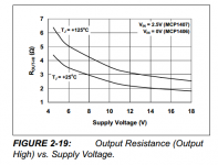
As for the MCP1407 getting "exponentially" worse when supply voltage decreases: the datasheet does not seem to agree. Here's a figure. Enthusiastic, energetic researchers can of course enter this data into a spreadsheet, fit a variety of linear and nonlinear trendlines, then extrapolate the best-fit equation to Vcc = 3.25 or thereabouts. And/or the data in other datasheet figures. If it is important.
_
Attachments
ok thanks. Mark's circuit flicks between no load (no current) and a given load. One that changes the load (for say, 1A to 1.1A analysis) would require some changes or perhaps simply having the variable resistance component connected across J4 and J2.
Of course you could make a fancy electronic load able to generate load steps and DC current, which would probably be a circuit with an opamp driving a transistor, and then when you observe something on the scope like settling time or slew rate, you never know if it is the regulator, or the electronic load, that you are measuring.
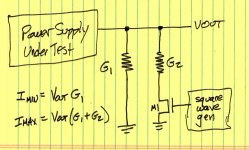
A dumb fast MOSFET switch and a dumb resistor is best. For DC current, a bunch of resistors and switches (or pin heaers or whatever) is alright, simple, works, and can't introduce anomalies in your measurement.
If you add a second resistor you can make the load current switch between Imin and Imax.A dumb fast MOSFET switch and a dumb resistor is best.
The math is slightly more convenient if you treat the resistors as conductances (G = 1/R) where the unit of conductance is the Siemens. Conductors in parallel are easy to compute.
When G1 > 0 (namely when the grounded resistor R1 is less than Infinity), the minimum current Imin is greater than zero ohms. When the MOSFET is off, some current still flows thru G1.
_
Attachments
If you add a second resistor you can make the load current switch between Imin and Imax.
Yep, easy and simple.
I've got a bunch of 8R macho power resistors from a dumpster, they're about half the size of my forearm, nice for testing amps and stuff.
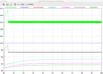
It's still bugging me that it takes a good 6 or 7 seconds for the 5V and 3V3 rails to come up to voltage spec, mainly because their respective Vrefs take so long to do so (in stark contrast to the 12V and 12Vref). Output from All With Rectification v3 Zobel.asc is attached (as is a zip with the model).
I know we touched on this before (post 198 and post 201)but I still don't get it. I removed the protection diodes thinking it would remove the tug-of-war mentioned earlier but it had no impact.
I know we touched on this before (post 198 and post 201)but I still don't get it. I removed the protection diodes thinking it would remove the tug-of-war mentioned earlier but it had no impact.
Attachments
I was about to do the silk screens and send the boards of when I wondered if it made sense for there to be a capacitor at the 12V input for the 5V and 3V3 boards. Any view?
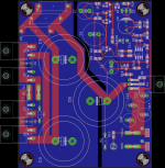
I have also rotated the board to fit better on the heat sink sidewalls. It also places the heat dissipating pass transistor more centrally on the heat sink. I've been busy working on the enclosure as well.
I have also rotated the board to fit better on the heat sink sidewalls. It also places the heat dissipating pass transistor more centrally on the heat sink. I've been busy working on the enclosure as well.
Attachments
Last edited:
What length spacers do you guys use when mounting power supplies, amp modules etc off heat sinks?
Obviously they shouldn't be so long that diode/FET leads don't reach the pcbs and need to be long enough to provide clearance for any parts tucked under the board.
They clearly need to be at least 5mm but 10mm seems like it would mean the bent leads of a TO-220 package would barely make it through the board for top soldering...
I prefer unthreaded spacers rather than threaded male-to-female standoffs. DigiKey 492-1104-ND has been my go-to choice. Nylon, 3.73 mm inner diameter, 6.35 mm tall (1/4 inch). Fits #6 bolt.
Hi
Toroidal transformer arrived today (230V primaries and 3 secondaries). It has a single "0v" connection lead which I understand is connected to the interwinding electrostatic screen.
I understand that this needs to be 'grounded'. I think this means it should be connected to safety earth (i.e. where the IEC inlet ground/earth is connected to the chassis) but I am unsure. Can someone please confirm as I have not wired a transformer with such a screen before?
Also, I'm wondering if this needs to be connected at all when using my Quasimodo to optimise snubber values. Intuition suggests it won't make much difference but again I am unsure.
Once I have my snubbers worked out I should be able to do the parts order for the PSU rails. I expect the boards will arrive any day now.
I have a bunch of toroids with screens (Antek part number AS-xxxx, S means Shielded or Screened) and I connect them to chassis "ground" at the same point where the IEC mains inlet {with integral RFI filter, like THIS} connects the incoming mains "ground" to the chassis.
One way to think of the screen is to consider it a capacitor plate. It's a solid sheet of conductor between the primary winding and the secondary winding.
Without the screen, there is a capacitance from primary to secondary. This injects "mains noise" (RFI) from the primary into the secondary, and is not desirable.
With the screen there are now two capacitances. One from primary to screen, the other from screen to secondary. If you ground the screen, "mains noise" (RFI) in the primary is harmlessly redirected to ground, and does not get injected into the secondary. This is desirable.
Of course if the transformer has multiple secondaries, the screen does not prevent capacitive coupling between secondary1 and secondary2. But at least this isn't "mains noise", it is "not-mains noise".
Last edited:
Thanks again Mark. I'm glad I was on the right track.
Off to measure my snubber resistors with my Quasimodo.
Off to measure my snubber resistors with my Quasimodo.
Mark and others.
The screen is an interposed capacitance.
Now insert an inductor in series with a resistance into the screen lead and connect that to Chassis. The Chassis is connected to Earth via a very large capacitance with substantially, air as the dielectric.
The filter is T shaped.
The Input from mains (left side) is Primary to Screen capacitance.
The Output to LV (right side) is Screen to Secondary capacitance.
The grounding leg (down side) is Screen lead inductance to Earth via a capacitance.
At one frequency the grounding lead will be a resonant series LC (plus a little r) and this impedance will be very low. At this one frequency the T filter will be very effective.
At all the other higher frequencies, the inductance of the Screen lead will dominate and the T filter will not be very effective. It will be very poor in the high MHz range and above. This effect may start in the low MHz range.
At all the lower frequencies the filter will be much more effective since these lower frequencies will pass along the inductive lead more easily. But the T filter is still not as good as when there is zero inductance in the screen grounding lead.
The higher frequencies that do not get attenuated will be passed to the LV side.
The screen lead MUST be very short and MUST be connected to Chassis at the transformer as close to where the Screen lead comes out of the Transformer. This short lead minimises the inductance. That reduces the resonant frequency of the grounding lead.
If one uses the long lead that comes as fitted, one is adding to the avoidable inductance and that ruins the effectiveness of the interference filter.
Last edited:
I just measured an Antek AS-3218 screened transformer that I had lying around (link)
Primary-to-screen = 275pF
Secondary-to-screen = 240pF
Screen wire = 22AWG stranded, 12.5 inches from tip to core
I measured a piece of 22AWG wire, 12.5 inches long. The meter reported 350nH which agrees pretty well with theoretical calculations (380nH). Measured resistance was zero; theoretical calculations say 0.015 ohms.
Plug the above numerical values into Andrew's slightly goofy filter topology (in my opinion he's got Neutral and Earth reversed*, but use it anyway), crank some Laplace analysis, and you'll find that the corner frequency, where the screen begins losing effectiveness, moves down by a whimpering 3.4X when you cut the external screen wire length from 12.5 inches to 1 inch. This result makes intuitive sense; corner frequency is proportional to 1/sqrt(L) and the square root of (12.5 inches divided by 1.0 inches) is 3.5. I don't think a shift of half-a-decade of frequency is anything to lose sleep over. Whether the filter corner is at 1MHz or 3.4 MHz is not crucially important.
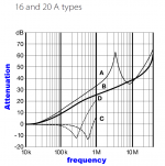
There is some good news: the upstream IEC inlet filter attenuation is getting better and better as frequency goes up, datasheet plot below. Shift the plot left-or-right by a half decade of frequency; it's still got loads of attenuation. The transformer screen attenuates primary-to-secondary noise injection by ~ 75dB or more below 100kHz. The IEC inlet filter kicks in and attenuates at higher frequency. Synergy!
A second piece of good news is that inexpensive ferrite beads can be sprinkled downstream if desired, giving mind boggling amounts of attenuation for those who lay awake at night worrying about 100 MHz mains-borne noise getting to the input terminal of their voltage regulator.
*maybe this is a US/UK difference of terminology
_
Primary-to-screen = 275pF
Secondary-to-screen = 240pF
Screen wire = 22AWG stranded, 12.5 inches from tip to core
I measured a piece of 22AWG wire, 12.5 inches long. The meter reported 350nH which agrees pretty well with theoretical calculations (380nH). Measured resistance was zero; theoretical calculations say 0.015 ohms.
Plug the above numerical values into Andrew's slightly goofy filter topology (in my opinion he's got Neutral and Earth reversed*, but use it anyway), crank some Laplace analysis, and you'll find that the corner frequency, where the screen begins losing effectiveness, moves down by a whimpering 3.4X when you cut the external screen wire length from 12.5 inches to 1 inch. This result makes intuitive sense; corner frequency is proportional to 1/sqrt(L) and the square root of (12.5 inches divided by 1.0 inches) is 3.5. I don't think a shift of half-a-decade of frequency is anything to lose sleep over. Whether the filter corner is at 1MHz or 3.4 MHz is not crucially important.
There is some good news: the upstream IEC inlet filter attenuation is getting better and better as frequency goes up, datasheet plot below. Shift the plot left-or-right by a half decade of frequency; it's still got loads of attenuation. The transformer screen attenuates primary-to-secondary noise injection by ~ 75dB or more below 100kHz. The IEC inlet filter kicks in and attenuates at higher frequency. Synergy!
A second piece of good news is that inexpensive ferrite beads can be sprinkled downstream if desired, giving mind boggling amounts of attenuation for those who lay awake at night worrying about 100 MHz mains-borne noise getting to the input terminal of their voltage regulator.
*maybe this is a US/UK difference of terminology
_
Attachments
Last edited:
I did not refer to Neutral and did not mean Neutral.
I meant Earth as in the thing we stand on, approx 12Mm ball
Thanks for putting some numbers to the resonant frequencies.
I meant Earth as in the thing we stand on, approx 12Mm ball
Thanks for putting some numbers to the resonant frequencies.
An excellent thread with some excellent references (post 6) and examples (post 11)
http://www.diyaudio.com/forums/equipment-tools/272068-chop-chop-box.html
Notice the metal heatsink inside the insulating chassis (!)
http://www.diyaudio.com/forums/equipment-tools/272068-chop-chop-box.html
Notice the metal heatsink inside the insulating chassis (!)
Interesting. I need to get back to the test circuit you suggested. The PSU boards arrived yesterday. I've still to do the snubber measurements (I was interrupted the other day), calculate the bleeder resistors, get my head around the test rig's layout on perf board and then place my parts order. I've done all the enclosure design and that's ordered.
- Status
- Not open for further replies.
- Home
- Amplifiers
- Power Supplies
- Adventures with 5A regulated voltage circuits