I have an Advent 300 which I've just re-capped and started to re-bias and do general service on. In going through the service manual re-biasing, all voltages appear to be to spec except one. The manual states that voltage at the emitter of Q110 and Q111 should be + and - 12v respectively, +/- 10%. Mine read almost 15v, which is the voltage regulator is set at.
Schematic attached
The manual makes no mention of how to adjust this voltage, and the schematic shows no adjustment pot. Do I need to replace R138 and R139, and if so, how do I calculate the replacement? (I'm much more a tube guy and don't really understand transistor operation all that well. Something else?
Thanks a ton!
Attachments
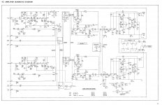
So did you measure the Voltages before or after the re-cap job? Q110 and Q111 are very elementary regulators referenced by Zeners D101 and 102. If the transistors aren't shorted (unlikely) it's possible you damaged traces on the board. If the caps were leaking the acid could have damaged the board before you got to it. You need to measure the Voltages on all 3 pins of the transistors and both pins of the Zener diodes. When operating properly I'd expect +12 on Q110 base and -12 on Q111 base. The emitters will be about 600 mV lower at 11.4 and -11.4. These can be 'off' by up to 10%.
If you change R138 and R139 why would you calculate a replacement? The original value was correct. If it makes you feel better, the resistor will dissipate E²/R so 3x3 /750 - around 8 mW so a 1/4 or 1/2 Watt resistor will be fine.
G²
If you change R138 and R139 why would you calculate a replacement? The original value was correct. If it makes you feel better, the resistor will dissipate E²/R so 3x3 /750 - around 8 mW so a 1/4 or 1/2 Watt resistor will be fine.
G²
Last edited:
So did you measure the Voltages before or after the re-cap job? Q110 and Q111 are very elementary regulators referenced by Zeners D101 and 102. If the transistors aren't shorted (unlikely) it's possible you damaged traces on the board. If the caps were leaking the acid could have damaged the board before you got to it. You need to measure the Voltages on all 3 pins of the transistors and both pins of the Zener diodes. When operating properly I'd expect +12 on Q110 base and -12 on Q111 base. The emitters will be about 600 mV lower at 11.4 and -11.4. These can be 'off' by up to 10%.
If you change R138 and R139 why would you calculate a replacement? The original value was correct. If it makes you feel better, the resistor will dissipate E²/R so 3x3 /750 - around 8 mW so a 1/4 or 1/2 Watt resistor will be fine.
G²
Thanks, Stratus46. Re: R138 and R139, I was guessing that they were dropping voltage and thereby setting the bias point (and maybe they had gone off after all these years), but like I said, I don't really understand transistors. Sadly I didn't think to measure these voltages before the cap replacement - I only did the most basic voltage measurements - live and learn!). The only trace damage I might have caused would have been in the phono stage at C114 and C117 (they are under a chassis frame member and hard to get at and hard to inspect). Caps were basically intact (no signs of failure or leakage).
I'll measure the base and collector voltages on them and report back.
I should probably mention that the schematic shows two 3000uF filter caps in the PS, but mine had one 4700uF (on the positive rail I thiink) and a 3000uF cap on the other. Appear to be original, but hard for me to tell. I replaced both with 3300uF caps per suggestions from a few people in the know. Can't imagine that that would cause this problem, but I don't know. Basic PS voltages are closer to the stated voltages with the new caps (but the old voltages weren't far off).
Carl
Carl
OK, so I was reading voltages wrong earlier (I'd forgotten to flip the pinouts while looking from the top...).
Q110:
e=10.33
c=14.9
b=11
Q111:
e=-10.14
c=-14.62
b=-10.86
Still not right, but better. I'll see if I can check the zeners. Don't know if it's possible to check for shorts in the regulator transistors but will see what I can do.
Q110:
e=10.33
c=14.9
b=11
Q111:
e=-10.14
c=-14.62
b=-10.86
Still not right, but better. I'll see if I can check the zeners. Don't know if it's possible to check for shorts in the regulator transistors but will see what I can do.
Thanks, djk. I may do that, though someone has suggested I replace the zeners with ones I've measured.
The absolue value of the voltage does not matter, as long as it's a couple of volts less than the input voltage.
I've been running this nice little receiver for a while now and it appears to be fine with the current voltage on the regulators (I may eventually replace the zeners but not for now). In fact, it's really quite nice.
I do have two more issues I'd like some input on. First, and worst, when I turned it on at some point after casing it back up, I got substantial pops when I touched the case or inputs. Sounds like it could be static discharge, but I've never experience that before, especially from a case. Eventually this stopped and hasn't returned. I've tried unplugging for a few days, but no pops when I try again.
I also get a noticeable mechanical hum and case vibration from the PS transformer. It's mostly just mildly annoying b/c from a few feet away it's not noticeable even at it's worst (depending on what it's sitting on). But I'm a little concerned there might be something going on that needs attention. I didn't notice any hum before the cap replacement, and the hum made me decide to check the case for voltage (thinking maybe there was some kind of leakage current?). It shows about a volt of AC when measured to house ground. I realize there could be some elevation due to wiring resistance, but I wouldn't think a full volt.
Schematic shows two 3000uF filter caps for the + and - supplies, and I replaced with two 3300uF. But the amp as I got it had a 4700uF cap on the + side, and I wonder if the smaller cap could be playing a part in this. I'll try replacing it when I can, but anyone know if that could cause a hum or have other ideas?
Thanks!
- Status
- Not open for further replies.
- Home
- Amplifiers
- Solid State
- Advent 300