Mr. Wavebourn recommended me to do this (bootstrap g2 to cathode with a capacitor). To do this, one should ensure a higher impedance g2 power supply, correct?
Yeah, the capacitor is going to store energy and you want to make sure that at all points in the AC cycle it is going to keep its voltage fairly constant. Driving into clipping will probably cause average screen current to rise and have the voltage across the capacitor sag a bit.
It would be bad to have a very low impedance screen supply because it would sink or source lots of current into/from the capacitor every time the screen voltage tried to rise or fall, which it needs to do because the voltage at the cathode is changing.
It would be bad to have a very low impedance screen supply because it would sink or source lots of current into/from the capacitor every time the screen voltage tried to rise or fall, which it needs to do because the voltage at the cathode is changing.
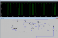
Hey folks, this is what I get with LTSpice and an optimized loadline for pentode mode of Ua/Ia * 0.9, like the 1.7k example I gave above.
To remind, Ua = 170V, Ia = 90mA, Vg2 = 170V
The output stage is driven into severe clipping. You can see the bottom waveform severely limited. I got a similar result with the KT88 model.
To remind, Ua = 170V, Ia = 90mA, Vg2 = 170V
The output stage is driven into severe clipping. You can see the bottom waveform severely limited. I got a similar result with the KT88 model.
Attachments
I just eyeballed a load line and it seems fairly symmetrical. I'm not exactly sure why you are seeing such asymmetry.
I don't really use sims, though. Maybe someone who does can offer better help.
Edit: Is bias shifting due to coupling cap charging at Vg=0? Can you eliminate the coupling cap on the input and just drive with an AC source with DC offset to set bias?
I don't really use sims, though. Maybe someone who does can offer better help.
Edit: Is bias shifting due to coupling cap charging at Vg=0? Can you eliminate the coupling cap on the input and just drive with an AC source with DC offset to set bias?
Last edited:
Bingo, the cap! Thanks so much, it works now!
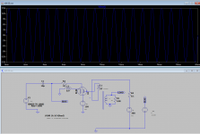
I chose the following -
300V B+,
150V on g2 screen
Approximately 3.8k primary impedance and 15% CFB
Power output is 10.8W at slight clipping with a Pdiss of 21.6W, which translates into 50% efficiency. Well, theoretical output should 47% efficiency, I guess the simulator is a bit off.
Btw, this tube can handle 21.6W.
DF is 10.
P.S. Now, it seems g2 and g1 need voltage regulation due to their high sensitivity. I'm wondering if I should go PP or SE on this.
Attachments
Last edited:
....which translates into 50% efficiency. Well, theoretical output should 47% efficiency....
No, theoretical is 50% (the difference between Sine and Square).
A safe-bet for Real Tubes (pentodes) carefully matched at at not-high THD is 40%. But you can get numbers from 20% to 55% by mismatching and letting THD soar.
My 826 SE amp hits 36.5% efficiency at full power (1.3% THD). When I was drawing load lines, I was calculating 44% efficiency.
Won't someone please wind me a transformer with no losses so I can hit that 44%?
Won't someone please wind me a transformer with no losses so I can hit that 44%?
A 5% total ohmic losses OPT should reduce power efficiency from 44.4% to 40%.
This is the range I'm winding my best OPTs.
In your case, you've got around 9% ohmic losses OPT.
An example of such OPT is:
0.2 Rdc at the 4R output ; or 0.4Rdc at the 8R output
140Rdc of a 3.5k primary
This is the range I'm winding my best OPTs.
In your case, you've got around 9% ohmic losses OPT.
An example of such OPT is:
0.2 Rdc at the 4R output ; or 0.4Rdc at the 8R output
140Rdc of a 3.5k primary
Last edited:
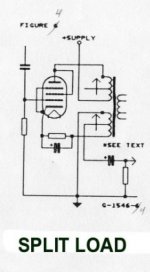
P.S. Here's a rectifying question for me. Despite the cathode winding be mentioned as a CFB one, it carries pseudo primary swing in phase as well, correct? Which means one should design the OPT with the following criteria:
1. The sum of CFB + plate winding in series will form the optimal load impedance and not the plate winding only?
2. The sum of CFB + plate winding in series will be used to calculate the operating flux density and power output?
Are the mentioned questions correct?
Thanks again!
1. The sum of CFB + plate winding in series will form the optimal load impedance and not the plate winding only?
2. The sum of CFB + plate winding in series will be used to calculate the operating flux density and power output?
Are the mentioned questions correct?
Thanks again!
My output transformer was the 25W Edcor 5k:8 model, which has a secondary resistance of about 0.45 Ohm and a primary resistance of about 80 Ohm.
As far as your questions go, for #1, yes. When designing my Unity-Coupled amp I treated the 1k plate winding and the 1k cathode winding as a 4k plate-to-plate load for load line purposes. So you add up all of the anode and cathode turns and use that to calculate the total impedance of the load the tube will drive.
For #2, I don't know as I'm not a transformer designer (I suspect the answer is yes) but I do recall that Patrick Turner walked through his 13E1 SE design on his website, which has a cathode winding. He may walk through these types of concerns. Have you read that?
I didn't check his 13E1 thoroughly and I will, thanks. It makes sense that the sum of windings (plate + cathode) be treated as a whole for flux density and power capability though.
Is the CFB winding kind of two-way job? The cathode provides a lower impedance swing to the transformer, but in the same time, the cathode winding provides a voltage feedback to the cathode?
Is the CFB winding kind of two-way job? The cathode provides a lower impedance swing to the transformer, but in the same time, the cathode winding provides a voltage feedback to the cathode?
Cathode feedback is series-applied voltage feedback. It is very similar to the non-inverting op-amp configuration except what is really cool about it is that there is no wasted power in resistors like there is with op-amps. The magic of transformers. 😀
Is the CFB winding kind of two-way job? The cathode provides a lower impedance swing to the transformer, but in the same time, the cathode winding provides a voltage feedback to the cathode?
The cathode winding is just another winding on the transformer. If it were connected in the plate circuit (in series with the other primary winding) it would make a conventional primary. You could even connect G2s to the windings' junction and call it "ultra-linear".
In plate plus cathode loading there is a special case where both have the same number of turns. This is done in the McIntosh and in the Crowhurst amplifiers, and the equivalent is done in the Circlotron (where they become a single winding!).
Your obedient serpent,
Chris
Well, cathode windings are in phase with the primary, but the swing is out of phase. So the cathode swing should not contribute to an increase of an AC flux density, it should even decrease it. But in SE stages DC flux density should by affected by both windings.
It might be more useful to think about how current flows through the (split) primary. The *same* signal current flows through *all* of the primary. So both sections of (split) primary contribute their share to signal flux. Does that make sense?
The feedback that comes with referencing G1 to signal ground seems to confuse the issue, but it's not inherent in a split primary design. Some amplifiers, including very early McIntosh's, had a tertiary winding of the same number of turns as the cathode part of the split primary. This referenced G1 to cathode, and removed the feedback effect. The output valves operated at full pentode gain (G2s were cross-coupled to the opposite output valve's plates) and full pentode output impedance, etc.
Or, another way to say it, is that signal voltage at the cathode is *generated by* the signal current flowing through that portion of the total loading on the valve.
Does that help, or would a different description work better?
All good fortune,
Chris
Last edited:
I guess I don't understand why you say that the swing is out of phase. Can you explain what you mean by that?
It seems that if the start of the plate winding is connected to B+ (AC GND) and the end is connected to the tube plate, and the start of the cathode winding is connected to the cathode and the end to GND, then they are driven in phase and will act as if it were the same number of total turns in the plate of a conventional SE transformer.
I hope what I was trying to say came across in that.
My bad guys. Yes, the CFB and anode coil share the same phase, I confused myself with the swing on the plate itself.
So, yes - the whole sum of CFB + plate primary should share the transformer flux.
Chris, excellent info on the McIntosh, thanks!
So, yes - the whole sum of CFB + plate primary should share the transformer flux.
Chris, excellent info on the McIntosh, thanks!
Half of Unity Coupling
Did this one about 20 yrs ago to get 600 Ohm output from a 6K6GT. Using a discarded UL OPT with separate primary winding's the reflected load to the 6K6 is 12K. This is simply a 'Proof of Concept', the OPT needs to be gapped for SE operation.
Did this one about 20 yrs ago to get 600 Ohm output from a 6K6GT. Using a discarded UL OPT with separate primary winding's the reflected load to the 6K6 is 12K. This is simply a 'Proof of Concept', the OPT needs to be gapped for SE operation.
Attachments
- Home
- Amplifiers
- Tubes / Valves
- Advanced CFB questions, limited power.