Hi folks,
My goal is probably naive, but thanks to the expertise of your all, let's find out.
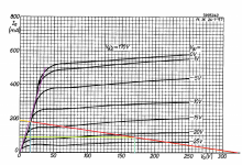
Let's start by taking a pentode. Let's say I'm choosing the PL36 just for example, to operate it in class A SE
I drew a 1.7k loadline, which thanks for the short Patrick Turner guides is chosen by the simple formula Rl = Ua/Ia*0.9
Ua = 170V
Ug2 = 170V (seen by the graph)
Ia = 90mA
Pd = 15.3W
By the graph, we can see a symmetrical loadline with a voltage swing of 310Vpp, translating to 110Vrms, resulting in a theoretical power output of 110^2 / Rl = 7.11W
And this results in a maximum efficiency of 7.11/15.3*100 = 46.5%. So far, so good.
Of course this operation is extremely non-linear and we need to apply feedback. Are we facing a small problem here?
From practice and simulations, I think yes. If we apply too much feedback, we will be limited in swing due to the small bias point, which is -Vgk = 22V by looking at the graph.
This is where I need your advice. I had this problem with deeper CFB where the bias point, due to the tube's nature, was not negative enough, limiting the power due to limited voltage swing.. For some time I though that not all tubes are suitable for pentode operation and feedback. But is this true?
If we take a look at the PL36 situation, we can deduce from the graph the gain is currently 7. When applying feedback, what happens when it becomes, let's say, 3. It will then need a bias point of Vgk -52V.
Does the bias point shift when the tube operates is CFB, as it is a pseudo-UL mode?
LTSpice gives the power back when I decrease the load. Of course this makes a lot of sense, because we're limiting the needed voltage swing for the same amount of power output.
Thanks folks!
My goal is probably naive, but thanks to the expertise of your all, let's find out.
Let's start by taking a pentode. Let's say I'm choosing the PL36 just for example, to operate it in class A SE
I drew a 1.7k loadline, which thanks for the short Patrick Turner guides is chosen by the simple formula Rl = Ua/Ia*0.9
Ua = 170V
Ug2 = 170V (seen by the graph)
Ia = 90mA
Pd = 15.3W
By the graph, we can see a symmetrical loadline with a voltage swing of 310Vpp, translating to 110Vrms, resulting in a theoretical power output of 110^2 / Rl = 7.11W
And this results in a maximum efficiency of 7.11/15.3*100 = 46.5%. So far, so good.
Of course this operation is extremely non-linear and we need to apply feedback. Are we facing a small problem here?
From practice and simulations, I think yes. If we apply too much feedback, we will be limited in swing due to the small bias point, which is -Vgk = 22V by looking at the graph.
This is where I need your advice. I had this problem with deeper CFB where the bias point, due to the tube's nature, was not negative enough, limiting the power due to limited voltage swing.. For some time I though that not all tubes are suitable for pentode operation and feedback. But is this true?
If we take a look at the PL36 situation, we can deduce from the graph the gain is currently 7. When applying feedback, what happens when it becomes, let's say, 3. It will then need a bias point of Vgk -52V.
Does the bias point shift when the tube operates is CFB, as it is a pseudo-UL mode?
LTSpice gives the power back when I decrease the load. Of course this makes a lot of sense, because we're limiting the needed voltage swing for the same amount of power output.
Thanks folks!
Attachments
I'm not a tube guy (but I'm a feedback guy ;-), but normally (negative) feedback lowers the gain. That means you need to have more input signal for a specific output, but the max output power should not change.
Can you see that in LTspice?
Jan
Can you see that in LTspice?
Jan
Of course, that makes much sense.
In LTSpice I get lower power output the moment I start adding (too much)? CFB. The way to compensate it is by lowering the load.
In LTSpice I get lower power output the moment I start adding (too much)? CFB. The way to compensate it is by lowering the load.
What do you mean by CFB? Are you feeding back output current instead of output voltage? In that case, you don't lower the voltage gain but the current gain.
Did you try just to increase input voltage to bring the power back up?
Jan
Did you try just to increase input voltage to bring the power back up?
Jan
1. CFB stands for Cathode feedback, it is usually done by a tertiary output transformer winding feeding some part of the primary swing voltage into the cathode. It's a voltage negative feedback and it also results in a UL operation, due to the cathode swinging from the POV of the screen.
2. Of course. I'm always increasing the voltage until hard clipping.
2. Of course. I'm always increasing the voltage until hard clipping.
Ahh OK, I thought Current Feed Back.
If you say that the bias changes, that must be because you have DC feedback? Have you tried AC only feedback?
Come on you tube guys, don't let us float like this! ;-)
Edit: this is cathode bias? In that case I believe the feedback impedance (which goes to DC ground) should have the same DC impedance as the cathode resistor you would use without feedback.
Jan
Last edited:
Not sure about the bias, it was just an assumption. 🙂
Btw, I forgot adding some DC resistance in my cathode feedback winding, which should introduce some cathode bias and help. Or not?
Otherwise I'm using fixed bias only in simulations.
Btw, I forgot adding some DC resistance in my cathode feedback winding, which should introduce some cathode bias and help. Or not?
Otherwise I'm using fixed bias only in simulations.
Not really following you, but maybe you're adding cathode windings without removing them from the anode windings? This raises the load impedance, so could be what you're seeing.
To keep things apples-to-apples, you'll want to end with the same *total* number of windings, anode plus cathode.
YOS,
Chris
To keep things apples-to-apples, you'll want to end with the same *total* number of windings, anode plus cathode.
YOS,
Chris
Hi, without CFB you need just 20Vpp to get full power (from -12 to -32 V circa, looking at the curves you posted), but when you add 10% CFB you need to add 10% of the anode swing to the grid signal, so approximately (320-20)/10 = 30 V more. Do you have enough gain?
Hey hey! Yes, it makes some sense now. Chris, I feel dumb to not tweak the primary coil impedance with the addition of the CFB winding.
zintolo, thanks a lot! I made a CFB sim using an excel CFB calculation sheet of a friend, and it turned out 10% of CFB is just near the edge - a gain of 6.5, which needs 50Vpp grid voltage to swing 325Vpp. But in this configuration, Rp seems to be around 600Rp, at 1700Ra there's a Rl to Ra ratio to 2.83.
In the end I guess I was greedy for wanting a high ratio for DF, but guess you can't have it with all tubes.
One way recommended by a diy audio member was to increase g2 voltage for a lower plate voltage, to allow headroom.
If the driver is capable of such a challange, you can give "Shade" feedback from anode to grid of the output tube (through the plate of the driver tube) and reduce even further the internal resistance of the output tube (plus linearize the output tube itself).
Maybe I'm not understanding correctly, but you seem to be implying that you will need to supply a greater negative grid bias with cathode feedback.
You shouldn't need to. The cathode feedback does not extend down to DC conditions as it only has effect at AC. DC gain is still the full pentode gain. That's a cool thing about cathode feedback.
You will need substantially more AC swing but the DC idle operating point can be determined from the pentode characteristics. If you want to get fancy, take into account the voltage drop of the cathode winding resistance.
SpreadSpectrum, this is what I've been thinking as well. But LTSpice for some reason doesn't. I even made new simulations yesterday.
The moment you start adding feedback to an optimized tetrode/pentode mode loadline, even if it's a Schade one, power diminishes.
The moment you start adding feedback to an optimized tetrode/pentode mode loadline, even if it's a Schade one, power diminishes.
I think we need to separate the arguments:
- DC operating point that is influenced only by the the DC resistance of the CFB winding, not by anything else (when I have no signal, if CFB resistance is zero, the tube has no effect);
- Output power considering the same input signal, that will be of course lower due to the fact that the cathode is moving together with the input signal;
- Output power at clipping that is lower as well because the curves tends to become more UL-ish (anode-to-cathode and screen-to-cathode voltages goes down while input signal goes up, because cathode goes up as well), so less plate swing is available from bias point to g1=0, so less power.
1. We can neglect this out of equation. The sims are done with zero DC resistance in the cathode winding.
2. We can neglect this too, I always compensate with the loss of gain and measure the maximum output power at clipping threshold.
3. This is the one we're looking at. So it would make sense to do other tests with higher B+, but keeping Vg2 the same?
Best regards!
2. We can neglect this too, I always compensate with the loss of gain and measure the maximum output power at clipping threshold.
3. This is the one we're looking at. So it would make sense to do other tests with higher B+, but keeping Vg2 the same?
Best regards!
I'd do a double simulation changing B+ and Vg2 to find some sweet spots to start with, then investigate further on each sweet spot.
For some reason I can't get the 47% theoretical power output even in pentode mode in LTSpice. Wondering what's wrong.
I think we need to separate the arguments:
- DC operating point that is influenced only by the the DC resistance of the CFB winding, not by anything else (when I have no signal, if CFB resistance is zero, the tube has no effect);
- Output power considering the same input signal, that will be of course lower due to the fact that the cathode is moving together with the input signal;
- Output power at clipping that is lower as well because the curves tends to become more UL-ish (anode-to-cathode and screen-to-cathode voltages goes down while input signal goes up, because cathode goes up as well), so less plate swing is available from bias point to g1=0, so less power.
Zintolo's third point above is probably what you need to look at. With pentode configuration, the voltage between screen and cathode must stay constant (this is easy without cathode feedback becuase both are referenced to GND).
I've seen some CFB pentode designs add a capacitor between screen and cathode to keep voltage constant.
If not, you will get some UL effect and max output will be reduced.
Assuming a screen is bypassed to ground, does that make much difference?
Bypassing g2 to ground rather than Cathode, I mean.
(I've done this before, mainly it was a connection error, but the affect on THD was probably slightly improved, so I left the error.)
Bypassing g2 to ground rather than Cathode, I mean.
(I've done this before, mainly it was a connection error, but the affect on THD was probably slightly improved, so I left the error.)
I depends on how sensitive the screen is on the particular tube and how much CFB is being used.
It should improve linearity a bit, but in my opinion CFB does this much better than the UL effect here. I'd much rather have the combination of the CFB linearity improvement and full output power of the pentode configuration.
But as you say, in some instances the difference may not be all that big.
It should improve linearity a bit, but in my opinion CFB does this much better than the UL effect here. I'd much rather have the combination of the CFB linearity improvement and full output power of the pentode configuration.
But as you say, in some instances the difference may not be all that big.
- Home
- Amplifiers
- Tubes / Valves
- Advanced CFB questions, limited power.