Hi, I came up with this circuit while experimenting on my SE-CFB amplifier.
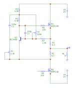
It is a so called Mu follower with adjustable bias current and AC gain.
First, the bias should be adjusted with P2 trimmer and then P1 should be used for adjusting the amount of ac gain.
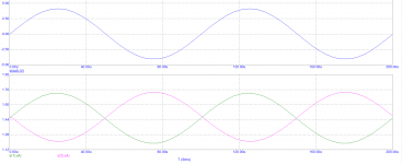
In the attachment you could see the effect on output currents of output transistors with minimum and maximum AC gain for 1W at 8 ohms load. You could also adjust P1 to the value you want and then use toggle switch across it to change min or max ac gain.
All in all ,the ability to change the AC gain from the front panel, on the fly is interesting, there is difference in sound and it depends on signal level, speaker impedance and so on.
The circuit is thermally stable and I haven`t seen any drawbacks while using it.
Cheers, Borko.
It is a so called Mu follower with adjustable bias current and AC gain.
First, the bias should be adjusted with P2 trimmer and then P1 should be used for adjusting the amount of ac gain.
In the attachment you could see the effect on output currents of output transistors with minimum and maximum AC gain for 1W at 8 ohms load. You could also adjust P1 to the value you want and then use toggle switch across it to change min or max ac gain.
All in all ,the ability to change the AC gain from the front panel, on the fly is interesting, there is difference in sound and it depends on signal level, speaker impedance and so on.
The circuit is thermally stable and I haven`t seen any drawbacks while using it.
Cheers, Borko.
Attachments

Last edited:

One interesting thing about this circuit:
You could adjust the same bias without P2 resistor and with higher R1 and R2, but then, AC gain adjusting with P1 won`t work.
When this kind of Mu follower is applied to the amplifier, with minimum AC gain adjustment, I get 7dB more loop gain 🙂
You could adjust the same bias without P2 resistor and with higher R1 and R2, but then, AC gain adjusting with P1 won`t work.
When this kind of Mu follower is applied to the amplifier, with minimum AC gain adjustment, I get 7dB more loop gain 🙂
This is very cool.
Just a question: Did you spend time looking at the effects of altering the ratio between R1 vs R2 ?
Just a question: Did you spend time looking at the effects of altering the ratio between R1 vs R2 ?
This is very cool.
Just a question: Did you spend time looking at the effects of altering the ratio between R1 vs R2 ?
No, didn't try that, but one could experiment with that part also. I guess the result depends on the choice of the lower gain device (mosfet/sit/bjt) and what you want to achieve.
The good thing is that R1 and R2 are low value 0R1 , so 2W resistors could be used with high bias currents, it's a good thing for headroom too.
- Home
- Amplifiers
- Pass Labs
- Adjustable "MuFollower"