Hi Johan,
I agree that the mixing of two (actually three, I think "enhanced" or "super" triode with boosted Vg2 even got mentioned too!) similar sounding but totally different schemes in this thread is causing considerable confusion here. My fault for commenting on the H & K paper in an inappropriate discussion, I should have started another thread. We have probably left John (the thread starter) in a serious brain spin, my appologies.
And yes, I agree on the confusion over "optimum" matching impedance. An optimum only showing up for power transfer, and at a bad match for distortion at that. What I should specify here regarding the H & K paper and UL discusision, is some factor say "Tau" times the tube Rp to be conserved for apple to apple comparisons.
Maybe Sy could split this UL/ H&K issue off into a new thread?
Maybe call it "Heretical Ultra-Linear thinking" or "Holy Cow under attack!"
Don 🙂
I just got home and saw two pages of new posts on this topic. I have been quietly experimenting with a technique that allows a continuously variable knob that goes from triode to pentode (variable UL percentage). I started with a circuit that bears a striking similarity to EC8010's napkin. In fact it is exactly the same.
There is a minor problem with that circuit. The plate is working into an inductive load (the OPT). Because of this the plate voltage will swing above the B+ voltage. If the pot is in any position other than pure pentode the mosfets gate will swing above the B+ voltage (the drain of the fet). This will cause extreme distortion, and possibly blowing the silicon fuse (mosfet).
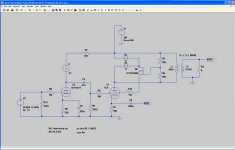
There is a solution to this issue, and it involves sprinkling a little more sand into the circuit. I am including a screen shot of the schematic. This has been added into an LTspice simulation of a SimpleSE amplifier. Everything works fine in the simulation world, but I haven't had the time to build it yet.
I tend to give circuits like this dumb names like PowerDrive. I call this one VariLinear. I have LTspice simulations of the unmodified SimpleSE and a SimpleSE with VariLinear. I have another simulation that seperates the DC and AC signals in the manner shown on the napkin. I haven't found it yet. It is on my old computer. I can post these if there is any interest.
There are no potentiometers in spice, so the pot is modeled as two resistors. You can play with the values to see the effects. If the resistor values are too low they will dissipate some of your valuable output power. If they are too large they will interact with the fets capacitance to cause a phase shift at high frequencies, leading to higher order distortions (ugly).
There is a minor problem with that circuit. The plate is working into an inductive load (the OPT). Because of this the plate voltage will swing above the B+ voltage. If the pot is in any position other than pure pentode the mosfets gate will swing above the B+ voltage (the drain of the fet). This will cause extreme distortion, and possibly blowing the silicon fuse (mosfet).
There is a solution to this issue, and it involves sprinkling a little more sand into the circuit. I am including a screen shot of the schematic. This has been added into an LTspice simulation of a SimpleSE amplifier. Everything works fine in the simulation world, but I haven't had the time to build it yet.
I tend to give circuits like this dumb names like PowerDrive. I call this one VariLinear. I have LTspice simulations of the unmodified SimpleSE and a SimpleSE with VariLinear. I have another simulation that seperates the DC and AC signals in the manner shown on the napkin. I haven't found it yet. It is on my old computer. I can post these if there is any interest.
There are no potentiometers in spice, so the pot is modeled as two resistors. You can play with the values to see the effects. If the resistor values are too low they will dissipate some of your valuable output power. If they are too large they will interact with the fets capacitance to cause a phase shift at high frequencies, leading to higher order distortions (ugly).
Attachments
Hi Tubelab,
Excellent point about the B+ being exceeded. I like your diode commutating solution too. I was originally thinking of just using a higher voltage source for the drain, but that would stretch the voltage rating of my 500V MOSFET to the limits. Voltage excursions for the MOSFET are likely to be a problem no matter what approach with only a 500V rating available.
One can also make a second voltage divider with a 50% divide point that splits the voltage from the drain supply to screen voltage in half. Then using two MOSFETs in series, the second one has its gate connected to the halfway point. Each MOSFET then drops half the voltage at all times. This idea can be extended to more series MOSFETs too, but two should be fine here.
Another problem for this test will be to come up with a variable range of load resistances for the tube plate. My output transformer stock here is very limited, and it might be best for this distortion spectra testing to avoid a transformer altogether. Using a bunch of power resistors could work, but will require twice the B+ supply voltage to simulate the voltage doubling of a transformer load. I have 600V available for B+. Also, it would be nice to be able to continuously vary the load resistance.
Still working on it:
There is a technique for making a variable power resistor using a MOSFET, source resistor, pot, and OP Amp. The Op amp compares the voltage on the MOSFET source current sampling resistor with an attenuated sample (using the pot) of the total voltage across the MOSFET. The Op Amp controls the gate of the MOSFET so as to maintain the pot attenuated sample of total voltage drop equal to the voltage on the source current sampling resistor. That way the total resistance is 1/(atten. ratio) times the source sampling resistor. This whole circuit has to float around at the plate voltage. This may require some effort to get debugged and stable. The Op Amp is not going to like flying around 500 V or so.
Another approach is to make a CCS for the plate that has some variable resistance across the CCS MOSFET to its gate reference voltage. (another resistor in the MOSFET source to B+ to set current) This makes the CCS current increase with voltage across the MOSFET, which looks like a resistance then. This is simpler, but does not give a perfectly linear resistance versus drain voltage swing due to the MOSFET gate drive being summed with the voltage reference. Putting an OP amp in to fix this ends up with the previous circuit. A bipolar transistor would come closer to linear due to its nearly constant 0.6V Vbe drop, but requires a lower value resistor divider from the collector (ie. 7W 100K Ohm Pot). Maybe a Darlington to reduce current drive.
Don
A couple of questions :-
The discussion so far seems to be concentrated on SE. I assume that this technique is equally applicable to PP, PSE etc.?
I had heard that this technique was developed by Tim de P. True??
Andy
The discussion so far seems to be concentrated on SE. I assume that this technique is equally applicable to PP, PSE etc.?
I had heard that this technique was developed by Tim de P. True??
Andy
Poynton: It' simply easier to do the tests on SE and the results are more easily interpreted. Distributed load was invented by Alan Blumlein.
smoking-amp: The variable resistance anode load isn't a problem at all. There's nothing to suggest that frequency affects this particular distortion in any way, so all tests can be done at 1kHz. Any output transformer is perfectly capable of accurately reflecting a 4:1 ratio of secondary loads at this centre frequency. So all you need is an adjustable dummy load...
This one is made of non-inductive (essential) metal film resistors. There are three parallel pairs of 10R 50W resistors wired in series with taps at each junction. That gives, 0R, 5R, 10R, 15R. After that are four 1R 20W series resistors tapped at each junction, giving 0R, 1R, 2R, 3R, 4R. Finally, a pair of 1R 20W in parallel, to give 0.5R. The upshot is a load that's variable in 0.5 Ohm steps from 0.5 Ohm to 19.5 Ohm, with a current rating of 4.47A on all settings. You merely need two leads to go to the load, and one link lead to obtain any setting you like.
Attachments
Hey-Hey!!!,
Don't neglect the higher voltage MOSFET's. FQP2N90 is a 900V D-S beastie, with a 30V g-s tolerance.
I have not measured my amps, but they're all U-L output and with efficient speakers I live around the 1W neighborhood most of the time. I can say that the first watt is *NOT* ruined, and when a few SE amps (which would not be efected by this effect ) are substituted, the PP comes out on top.
Class A operation, conservative operation at ~75% of dissipation ratings may help. The E-Linear driver/FB scheme (also pentode/faux pentode ) may play a part in it.
I have got my output TX with multiple taps for U-L/E-L opertation. The Peerless S-265-Q I had copied by Heyboer happens to have easy end-of-layer access in 10% increments. 20, 30 and 40% taps were installed. I can run the E-Linear front end from one set of taps and g2 from another. It is nice for doing science experiments...🙂
cheers,
Douglas
Hey all,
I just logged in to find the continuation of the interesting posts on the "Triode Trick" thread & I found all you big boys have taken my ball and gone to play over here.
So I'm here to just look on from the sidelines & see if I can pick up anything - I'm very interested in the outcome of all your experiments.
My original intention for the thread was to experiment with triode-strapping but this outcome is more than I expect - the possibility of an adjustable UL operation using existing OPTs
Keep up the good work.
John
First, thanks goes to our moderator for splitting this thread out. This will eliminate some reader confusion hopefully.
I do have some ST P2NK90 900V MOSFETs on hand, fairly similar to the FQP2N90. Since we are powering the gate from an output tube in source follower mode, the ~400pF gate capacitance shouldn't be a problem. Or I can just use two FQP1N50's in series mode, 115 pf gate Cin then.
As Sy suggested, the monotonically increasing screen current with lower plate voltage swing in SE should produce mainly even harmonics. Operating P-P mode in class A will eliminate these even harmonics without generating much odd harmonic. So this is likely to explain Douglas's amplifier experience. Also there is the effect of global feedback to consider too.
My comment about the first watt being the worst watt was meant for the typical class aB operation of most UL amplifiers marketed. These will cancel the even harmonics, but will convert some to odd harmonics in class aB mode. What may save them is that these "even harmonics converted to odd harmonics" effects in P-P generally show up at larger amplitudes. A SE test should be good at revealing what is going on here. One also has to wonder what effect smoking the g2 grid has on tube longevity.
I have a Hammond 1640SE transformer, but it has a lowish 1.25K OHm primary.
I also have a Hammond 1650T P-P transformer, again lowish 1900 OHM CT primary, 120W. Could put a CCS on the other half of the primary to balance the current.
(note: Hammond and many other xfmr manufacturers rate their xfmrs wattage at close to magnetic saturation. And guitar amp ones at beyond that. When one backs off to where the maximum permeability occurs, these wattage ratings get cut by 1/2 to 1/3, so this is more like a 50W "reality" Hi-Fi transformer)
And, I have an Edcor CXPP100-SP1 P-P transofrmer, 5K OHM CT primary with isolated 20% UL/CFB windings (the other 80% windings are split/isolated too), 100W. CCS on the other half again to balance current. (Again, 40W "reality" Hi-Fi transformer)
I have an 8 OHM load resistor, 100W, with 1 OHM taps.
Also, have a 24 bit M-Audio sound card for spectrum measurements, and AudioTester software V2.0
Probably the Edcor is the way to go here for this testing.
OH, and welcome to the discussion John, I didn't mean to leave you out, I just thought we were hi-jacking your original thread.
Don🙂
progress report
I have rounded up the Edcor CXPP100-SP1 (5K OHM CT P-P) output transformer for the testing. I will use an ST P2NK90Z MOSFET for the balancing current source on the second half of the P-P primary. (so SE mode for the tube)
I have three pentodes that allow high screen voltages: 6BQ5/EL84 (it has a suppressor grid), 6HB6 (have both suppressor and beam versions), and 6L6GC (beam ). I will use an Optimos SS amplifier to amplify the sound card signal to grid1 drive levels. And I will use a 2nd ST P2NK90Z MOSFET (900V) to buffer (source follower) the g2 drive from an attenuated plate signal with separate DC level adjust. (I will use a 600V supply for the MOSFET drain supply, explained below.)
Some comments:
The screen current is not re-inserted into the UL primary tap with this adjustable %UL scheme. Hafler and Keroes' article correctly comments that re-inserting the screen current into the UL tap reduces distortion. The BEST (perfect actually) solution would be to re-insert screen current from the MOSFET drain to the plate/primary connection, but voltage levels do not cooperate on this.
(This is an area that requires some additional work for this variable %UL scheme to succeed in the longer run. I was going to use Tubelab's diode cummutation scheme for the drain connection, but later realized that this will cause abrupt distortion as the drain current switches from B+ to plate/primary connection. So some re-thinking called for on that approach. )
This all points towards the necessity of reducing the DC level on the screen to avoid this non-linear screen current capture of plate current whoes in the first place. I might also add that the usual CFB setups also suffer from screen current distortion problems, but at least they provide for easy lowering of the screen DC level to minimize this.
I will take a spectrum and scope trace of the screen current while testing, so we can see just what we are dealing with.
I just read thru H & K's article again and also Williamson & Walkers article "Amplifiers and Superlatives". It is now clear to me how H & K arrive at their "optimum" %UL.
Looking at their graph (fig. 2):
http://www.tubecad.com/Classic_Articles/page4.html
The High Level distortion curve is the main curve really confining their selection, although the power curve does some too. This huge upswing in distortion is caused by g1 grid current drawn, trying to maintain the power output curve (which is really an arbitrarily selected curve set by their input signal level). Does anyone really believe that triode distortion is off the chart as they present it? They simply overdrove the triode to get this. (I don't see how they could keep a straight face and present this data!)
This is all due to the fact that the fixed transformer primary impedance is too high at the triode end of the chart where there is lower tube Mu, to get much power output.
The power curve as shown should really be dropping off faster toward the triode mode end if they had avoided overdrive, since the fixed impedance primary is becoming progressively too high to get much power out of the triode.
The Low Level distortion curve presented shows the more realistic case for distortion trends when overdrive is avoided.
The rapid rise of low level distortion toward the pentode end is due to the fixed primary impedance causing the high-Mu pentode to enter 3/2 power current operation into a low impedance (relative to the pentode's Rp). One can get more power out in this regime, but it depends on additional circuit gain elsewhere and global feedback to fix it then.
If one were to recognise that the tube's effective Rp (see the internal impedance curve in fig. 2. The flat top on the pentode end is due to the small plate effect taking over from the larger screen effect when %U goes to zero, the rest of the curve goes as 1/%U) and the tube's effective MU, varies closely as 1/%U, then a diiferent experimental setup would be indicated.
Normal triode design uses a plate load of some factor, say Tau, greater than the plate resistance. This is a compromise, as lower Tau (till Tau = 1) gives more power, and higher Tau gives less distortion. (The distortion is due to the plate Rp varying with signal) If we were to compare different Mu triode tubes, the only fair comparison is to use the same Tau factor loading for each. Apples to apples as they say.
Re-doing the H & K's chart using constant Tau (ie. the primary impedance Z would have to vary as 1/%U on the bottom axis ) should give constant power out, and constant distortion (assuming the same tube idle current setup) for the same power level across the graph. The pentode end then does not jump to higher power since we are not entering 3/2 power current mode either. (of course, infinite Z primary impedance would be impractical for pentodes, so one would not use low %U taps in practice.)
(sorry to be so long winded, but this UL stuff is complex)
Don
The High Level distortion curve is the main curve really confining their selection, although the power curve does some too. This huge upswing in distortion is caused by g1 grid current drawn, trying to maintain the power output curve (which is really an arbitrarily selected curve set by their input signal level). Does anyone really believe that triode distortion is off the chart as they present it? They simply overdrove the triode to get this. (I don't see how they could keep a straight face and present this data!)
That's an interesting point, BUT... for true apples to apples comparison at high levels, their approach is valid, I think. If I have a UL amp that shows 1% nonlinearity at 10W, but the triode amp is already clipping, then indeed I've gotten a significant distortion reduction. Power amps supply power, and for the same power supply and output tubes, if one amp is clipping away and another is still well below grid current, the latter has performed better in that regard. The thrust of their graph is just that- there's a screen ratio where one can get the majority of pentode power, a point at which the triodes are already in full collapse.
To your point, it would have been interesting to pick a power just below the triode clipping point, adjust the p-p loading for each, and use that for a reference, just to see how the distortions compare. But we can get that off of datasheets (especially the excellent ones from Mullard), and at least in the examples that come to mind, the high-level performance of UL still trounces triode, even when operating within the clipping limits.
MUCH more interesting (to me) is what happens at low levels.
Hi SY,
Your point is taken. Clearly the H&K paper is from the era when max power output per cost reigned supreme. And the UL scheme does squeeze out the most power from a given output tube. However, this extra power comes at a hidden cost here. Their curves are apparently for their complete amplifier, including input stages. The higher power in UL necessitates greater gain in the global feedback loop to overcome the heavier 3/2 power distortion generated in UL (or pentode) (compared to a non-overdriven triode). The triode circuit might save an input tube for the same distortion spec. and so allow the purchase of a slightly larger output tube.
But I agree, the first watt quality is really the more important criteria. So we test...
Don
Elimination of Screen current distortion!
It just occured to me that the MOSFET follower (for the screen drive) can have its drain terminal connected to the plate/primary connection IF the DC level of the screen is reduced (from the plate DC level) slightly more than the UL% reduces the peak screen voltage swing.
Example: lets say the plate is swinging 100 to 300 V (200V DC average) and the screen UL% is 50%, so the screen will be swinging + and - 50V around its DC level. If its DC level is reduced by more than 50V below the plate DC level, then the MOSFET has some headrome to operate. Let's say DC screen set at 140V, so the screen varies 90 V to 190V. The 90V minimum staying below the 100V minimum of the plate. And the 140V max. staying below the 300V max of the plate. (In P-P the DC MOSFET current component will cancel in the xfmr.)
This scheme won't help for my present testing, since I need to check for screen operation up at plate voltage levels, but this will work for other practical variable %UL amplifiers that use output tubes with reduced screen voltage operation, like TV horizontal and vertical outputs. Ironically, their reduced screen DC level already mostly fixes the screen current distortion problem anyway, but this zeroes the effect altogether. Hi-end specs!
Hmmm...., alternatively, one could put a floating positive boost supply on the plate(s)/primary(s) to power the MOSFET drain, again a little more boost than the %UL reduces the peak screen swing. This WOULD work for my present experiment I think. Have to check this out. Got some nice Power-one 150V, 200V, & 250V linears and some similar Acopian linears setting on the shelf here. Tempting, have to check their float voltage ratings. Where's that isolation xfmr. at?
Don
I am still hunting for the promised GE UL graph set for KT88 and will not say much now, but the graphs I mentioned earlier gave max. output available (i.e. just before onset of g1 current) at several different primary impedances (also my own tests). These do not at all change the behaviour with different g2-taps greatly, apart from obviously giving different output figures.
Then I am a little perplexed by the concern for what happens at low output. Why would we expect anything disasterous there? Both the triode and pentode operation give expectedly low figures; UL shows a smooth transition from pentode to triode at higher output powers, so why this fear of a sudden inconsistent aberation? We have some Ia/Va characteristics for power tubes at UL operation. Is anything evident there? I fear I fail to see why e.g. distortion products would be say 20mV at pentode side, but suddenly jump up to 100mV or whatever we fear somewhere inbetween, only to come down again to say 10mV. The whole theory as well as tests go against the expectation of any discontinuity.
What am I missing? Forget about H and K if they are unpopular; is there also a reason to doubt Peter Walker, later graphs from GE (KT66 and KT88) and Mullard (EL84 and EL34)? I always both presumed and found that manufacturers will give moderately accurate data regarding their products. I am all for experimenting (I earned my salary as a researcher), but with respect, why do I feel that we are re-inventing the wheel here?
________________________________________________
(Saw I took long to say "not much"! Moderator allowing: It is a little like Churchill: The "Times", once outraged at something Sir Winston did, wrote a 2 column report stating that they are speechless. Said Sir Winston: "The Times is speechless and takes 2 columns to express its speechlessness.")
Re: Elimination of Screen current distortion!
Smoking-amp,
I totally follow the above (to give a comment closer to what you intend doing than the previous post). And you state this only as an experiment. But how far can we decrease Vg2 in favour of decreasing its dissipation etc, before we loose what we gain by a higher Va? I do not have much data for power tubes at many different g2 voltages, but just off the memory I have an impression that one cannot lower the Vg2 a lot before loosing any output gained by a higher Va. Or are you arguing transmitter tubes and say 400Vg2 and 800Va or such (sorry if I missed this earlier)?
Regards.
smoking-amp said:Example: lets say the plate is swinging 100 to 300 V (200V DC average) and the screen UL% is 50%, so the screen will be swinging + and - 50V around its DC level. If its DC level is reduced by more than 50V below the plate DC level, then the MOSFET has some headrome to operate. Let's say DC screen set at 140V, so the screen varies 90 V to 190V. The 90V minimum staying below the 100V minimum of the plate. And the 140V max. staying below the 300V max of the plate. (In P-P the DC MOSFET current component will cancel in the xfmr.)
Smoking-amp,
I totally follow the above (to give a comment closer to what you intend doing than the previous post). And you state this only as an experiment. But how far can we decrease Vg2 in favour of decreasing its dissipation etc, before we loose what we gain by a higher Va? I do not have much data for power tubes at many different g2 voltages, but just off the memory I have an impression that one cannot lower the Vg2 a lot before loosing any output gained by a higher Va. Or are you arguing transmitter tubes and say 400Vg2 and 800Va or such (sorry if I missed this earlier)?
Regards.
Sorry for over-exposure,
but just before ducking I found the GE graphs for KT88 in UL operation on the following:
www.webace.com.au/~electron/tubes/ulo.html
Go down past the first circuit diagram, and the first graph set is it. It does not state in the caption that it is p.p. KT88, but those are the ones.
Regards
Edited: Spelling in www-address
Hey-Hey!!!,
At the mention of Walker, and if you'll take an IIRC for references...🙂 his amp was running ~11% U-L thanks to it's 1/9 CFB/tertiary winding. It was also good for reducing 3rd HD more than the amount of FB in the cathode winding could account for.
I wish I could account for all these with good ref's but 'I read it somewhere whilst researching tube circuits' is the best I can do today. The source looked good enough to trust when I read it.
The good performance of Walker's amps matches my own building with only CFB in the output TX. Dynaco, Acro and most recently Chicago Iron has yeilded some nice amps. I have moved to DH amps, so low capacitance filament Iron will be needed to execute the next one, built with 813's and the B0-14.
cheers,
Douglas
Hi Johan,
We changed the name of the thread so no one could find us! (Just kidding)
I think I need to explain my position some since some questions keep coming up that I didn't think were applicable to my complaints. First of all, I am not doubting the Hafler-Keroes paper as far as their results for getting more power in ultralinear or the manufacturers data sheets on UL either for that matter. In fact I don't think I ever mentioned power at all in the beginning. Some confusion is likely due to my dropping into an existing thread without having read it first too, to see where everyone else was coming from, and it seems power was a big concern in the earlier discussion.
I simply had finished working out the formulas for the effective Rp and Mu for the UL and CFB cases, and they come out quite interestingly and even beautifully. The results show that UL and CFB designs are absolutely equivalent to triodes. The UL scheme giving effective MU's that are between the triode wired Mu rating and the Pentode effective MU, depending on the %UL tap position.
Effective Rp's also being between the triode wired configuration and the pentode one. Ignoring a small plate term, the UL results are Mu = Mu_triode / (U%) and Rp = Rp_triode / (U%).
The CFB case gives similar results for effective Mu and Rp but for LESS than the triode wired Mu and Rp. So CFB and UL are really complimentary techniques for tuning a tubes MU and Rp.
The Hafler-Keroes paper is annoying (to me anyway) because it does not give any indication of the underlying simplicity of the results. In fact they seem to be at a loss to explain them. And their method of over driving the tube makes any %UL tap above 50% look like a horror show for distortion. They don't give any results for other primary impedances, so the reader is left with the impression that only a 43% tap (18.5% impedance) will ever work. As a result, we have endured years of UL tapped transformers with only 43% taps on them.
So #1 item to be tested is whether other tap % are useful and whether they obey the effective Mu and Rp formulas. Maybe H-K will be right on the 43% only, but I doubt it. If other % taps work as expected, then variable tapping via active screen drive will be an interesting new hobby for some.
My second complaint about the H-K paper is their condoning of just using a tap on the primary instead of a tertiary winding that would allow lowered screen voltage. No doubt one will get more power by scorching the g2 grid at B+, the manufacturers loved it.
My complaint is about likely distortion with this scheme. Screen current skyrockets as it approaches the plate voltage, as can be seen on virtually any pentode plate curves (that's why the plate curves drop off suddenly on the left side, the screen swallows all the current). This screen current is captured plate current that is then put back into the primary at a reduced # turns, so it lowers output power, and will produce distortion if it varies as a percentage of plate current. (and it certainly will from inspecting any of those plate curves again)
Setting the screen DC equal to the plate DC at the idle condition, by using just a primary tap, means that this mechanism is at maximum effect for the first watt. Now it does seem likely that this is monotonically varying even harmonic distortion, and so will be nulled out by P-P operation. But depending on biasing (class A or class aB) Some of this even harmonic distortion will get converted to odd harmonic. For SE operation, I would expect horrible results. I would guess some purists will want to know if P-P is cleaning up some horrible mess and increasing odd harmonics as a result.
So test #2 is to check for grid2 current distortion (spectrum) versus DC level vis-a-vi the plate DC level. And it also would be interesting to see if the earlier mentioned scheme of connecting the screen driver MOSFET drain to the plate/primary point will remove it.
That about covers it I think.
Don
Ultralinear + Cathode feedback
I am about to start build of a couple of monoblocks using Plitron VDV2100-CFB/H Output Trannies I've had sitting around for a few years.
These are:
2000 Raa
33% U/L taps
Separate 10% cathode feedback windings
5 Ohm secondary which is center tapped (another cathode feedback option)
100W rated (-3dB power @ 23Hz)
-3dB High frequency at 290kHz
Am I right in thinking that if I use the 10% cathode feedback windings in the cathodes of the output tubes and the 33% Ultralinear screen taps then I will effectively get 43% Ultralinear anyway (cause the screen to cathode volts will be 10% + 33% being opposite phase)?
Any advise on ouput tubes?
KT88, 6550 would give more power output than the transformer is rated for BUT I have Chinese and JJ KT88 and Sovtel 6550 on the shelf
EL34 is too "Old Hat" although I have heaps of them.
Perhaps KT77? I have some JJs.
Also have a pair of Mennos VDV70/100 monoblock amps (100W version with PAT4006) using triode strapped El34s which could serve as test beds. Now if only I had a distortion analyser!!!!
Cheers,
Ian
10% + 33% = 43%
Sounds right to me. This 43% magic # from UL designs is likely only applicable to 6L6 or related tubes (KT88 etc) in UL. Probably not meaningful for CFB particularly. For any tubes that have high Gm2 / low screen voltage ratings, I'm pretty certain this 43% number is too high for UL, but who knows what it does for CFB. The grid1 CFB effect is much greater than the screen UL effect due to the much higher Gm1 than Gm2.
Don
OK, this seems like the best time to ask this, I've read in the past Grimwood's ideas about so called optimized ultra linear operation. His claim (and he has no number to support this) is that the "optimum" ratio of UL operation to use with any particular tube depends on the physical geometry of the tube itself. Read it here:
http://www.webace.com.au/~electron/tubes/ulo.html
I have heard that some of his other ideas are a bit questionable, but this article seems reasonable enough. He also claims (once again, with no data) exceptional performance out of tubes that are notoriously difficult to work with in HiFi operations (2e26, 6146, etc.) Is there a way in your testing to see if the so called optimums fall where he says they should base on tube geometry?
Isaac
- Home
- Amplifiers
- Tubes / Valves
- Adjustable distributed load discussion