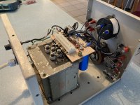
I put together this hi voltage bench supply from mostly parts I had hanging around. It turns out to be very useful for other purposes like safely/gradually powering up a direct coupled amplifier or reforming large power supply caps. The only purchased parts were the variac and some high voltage banana jacks.
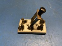
I think it came out pretty nice. Kinda looks steampunk on my bench. With that in mind I plan to add a DPDT knife switch on the front panel to control whether the high V is turned on in one position or the filter caps get quickly discharged in the other. To make this touch safe, (exposed conductors) I'll need a relay, perhaps solid state.
It has:
1. A high Vdc section, up to 550vdc at 100ma, that outputs to a stepped RC filter arrangement like you would see in a typical tube amp plus an array of output jacks for distribution.
2. Raw adjustable AC from the variac available at a pair of Jacks.
3. Two tube filament 6.3VAC at 1.7amp supplies distributed with a pair of jacks.
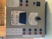
4. A large meter movement that displays the main B+ DC value.
5. A knob to control the main B+ DC amplitude.
6. Mains is fused on the back. I may replace this with a circuit breaker.
The design uses a variac connected to the primary of a large 500VAC transformer.
How about those slick graphics? - printouts taped over with shipping tape.
I think it came out pretty nice. Kinda looks steampunk on my bench. With that in mind I plan to add a DPDT knife switch on the front panel to control whether the high V is turned on in one position or the filter caps get quickly discharged in the other. To make this touch safe, (exposed conductors) I'll need a relay, perhaps solid state.
It has:
1. A high Vdc section, up to 550vdc at 100ma, that outputs to a stepped RC filter arrangement like you would see in a typical tube amp plus an array of output jacks for distribution.
2. Raw adjustable AC from the variac available at a pair of Jacks.
3. Two tube filament 6.3VAC at 1.7amp supplies distributed with a pair of jacks.
4. A large meter movement that displays the main B+ DC value.
5. A knob to control the main B+ DC amplitude.
6. Mains is fused on the back. I may replace this with a circuit breaker.
The design uses a variac connected to the primary of a large 500VAC transformer.
How about those slick graphics? - printouts taped over with shipping tape.
Attachments
Nice. One thing i would add is a current meter so you know what the load is drawing, will be very useful in the long run.
I use a Heathkit IP-2717 high voltage supply which has a standby switch to disconnect the HV, however i always always always unplugged the + cable before going into the device under test. Breaker switches and all that are technically great, but physically unplugging is the best insurance against user error.
I use a Heathkit IP-2717 high voltage supply which has a standby switch to disconnect the HV, however i always always always unplugged the + cable before going into the device under test. Breaker switches and all that are technically great, but physically unplugging is the best insurance against user error.
Last edited:
Nice execution Duncan2. I especially like your "single-point terminals on PCB construction" method.
Those terminals are apparently insulted from the mounting surface?
The clad copper PCB resembles a GND plane.
Both you and mcandmar highlighted the use of a current meter which I will add to my unit.....and the regraduate the dispay method - cool!
I'll have to look that up.
Those terminals are apparently insulted from the mounting surface?
The clad copper PCB resembles a GND plane.
Both you and mcandmar highlighted the use of a current meter which I will add to my unit.....and the regraduate the dispay method - cool!
I'll have to look that up.
Lovely build, you can tell a lot of effort went into that...
Nifty build, a HV PSU is invaluable.
That said I do go through a lot of fuses,it can get expensive (luckily I have about 3000 Russian NOS fuses), so a circuit breaker makes sense. Best thing to do is test said CB and see how it performs.
Andy.
I'd keep the mains fuse and fuse the HT with a small fast fuse. Circuit breakers in my experience don't act fast enough and aren't available in small enough current ratings.Mains is fused on the back. I may replace this with a circuit breaker
That said I do go through a lot of fuses,it can get expensive (luckily I have about 3000 Russian NOS fuses), so a circuit breaker makes sense. Best thing to do is test said CB and see how it performs.
Andy.
That is clean. Might need to make this for the bench this year. Thanks for sharing!
- Status
- This old topic is closed. If you want to reopen this topic, contact a moderator using the "Report Post" button.
- Home
- Amplifiers
- Power Supplies
- Adjustable B+ Bench supply for tube amp experiments