Hi All,
My on going project is to build a bench power supply with these specs :
- Two CV Outputs
- Adjustable Output voltage from 0V to 24V DC (fine+coarse)
- Rated Output current of 1 A
The circuit is currently composed of :
-22V/100VA double secondary transformer (2.27A each secondary)
For one channel :
-one LM338K in TO-3 (improved LM317) for current limiting
in serie with
-one LM338K in TO-3 (with heat sink) for voltage adjust
The problem that i have is, of course, heat dissipating...
For example : output 12V @ 1A, the heat dissipated by the last LM338K is
P=(30V-12V)x1A=18W
30V corresponds to 22V*sqr(2) - 1V (diodes bridge drop)
Junction temp is given by
Tj=(rthjb+rthra)*p+ta=(1+10)*18+25=223°C > 125°C -> the IC will thermal shutdown
where rthjb is the thermal resistance of the LM338K
and rthra thermal resistance of the heat sink (no air flow)
So what i want to do is keeping constant dropout voltage across the linear regulator in order to remove the thermal problem.
To do this, the best solution is to use a tracking pre-regulator which keep constant voltage between its output (connect to linear regulator input) and the final output.
I bought recently a SMPS adjustable step-down module based on LM2596S, see link below
2pcs LM2596 DC-DC Step Down Adjustable Power Supply Module | eBay
This IC (and others) has a FEEDBACK pin which is used to program output voltage with a resistor divider between output and ground.
Now the final question is : what is the best schematic you can show me to monitor final output voltage of the linear regulator with this feedback pin? Maybe OPAMP circuit...
(you can show me another kind of step-down IC)
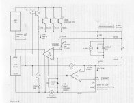
(see attached my current design + link to LM2596 datasheet)
http://www.ti.com/lit/ds/symlink/lm2596.pdf
Thanks in advance 😉
My on going project is to build a bench power supply with these specs :
- Two CV Outputs
- Adjustable Output voltage from 0V to 24V DC (fine+coarse)
- Rated Output current of 1 A
The circuit is currently composed of :
-22V/100VA double secondary transformer (2.27A each secondary)
For one channel :
-one LM338K in TO-3 (improved LM317) for current limiting
in serie with
-one LM338K in TO-3 (with heat sink) for voltage adjust
The problem that i have is, of course, heat dissipating...
For example : output 12V @ 1A, the heat dissipated by the last LM338K is
P=(30V-12V)x1A=18W
30V corresponds to 22V*sqr(2) - 1V (diodes bridge drop)
Junction temp is given by
Tj=(rthjb+rthra)*p+ta=(1+10)*18+25=223°C > 125°C -> the IC will thermal shutdown
where rthjb is the thermal resistance of the LM338K
and rthra thermal resistance of the heat sink (no air flow)
So what i want to do is keeping constant dropout voltage across the linear regulator in order to remove the thermal problem.
To do this, the best solution is to use a tracking pre-regulator which keep constant voltage between its output (connect to linear regulator input) and the final output.
I bought recently a SMPS adjustable step-down module based on LM2596S, see link below
2pcs LM2596 DC-DC Step Down Adjustable Power Supply Module | eBay
This IC (and others) has a FEEDBACK pin which is used to program output voltage with a resistor divider between output and ground.
Now the final question is : what is the best schematic you can show me to monitor final output voltage of the linear regulator with this feedback pin? Maybe OPAMP circuit...
(you can show me another kind of step-down IC)
(see attached my current design + link to LM2596 datasheet)
http://www.ti.com/lit/ds/symlink/lm2596.pdf
Thanks in advance 😉
Attachments
If you want/need 0V as minimum then it adds complication to the design.
If you settle for around 3Vdc minimum up to 20Vdc maximum then the design is simpler.
A 2.27Aac transformer feeding a capacitor input filter (normal rectifier+smoothing capacitor) the maximum continuous DC current available is ~1.13Adc. At this output the transformer is running at full rated capacity and will run hot.
If you want reliability and cooler running, then I suggest you use no more than 0.6Adc on a continuous duty and keep the reserve for low duty cycling.
As AndrewT said. 0V adds a bit of simple complication. All the reference circuitry needs to be connected below 0V so that, (to that circuitry) 0V is actually a positive voltage.
Think of it like a PSU that is actually operating from -3V to +30V. The -3V is unobtainable but, you are after 0V which is now obtainable.
Think of it like a PSU that is actually operating from -3V to +30V. The -3V is unobtainable but, you are after 0V which is now obtainable.
Ok thanks to comments but my only question is about the smps connected with the linear regulator...
I've heard that some linear regulators would get upset with HF noise at their input.
I've not experimented with this but you may need a CLC filter to clean up the SMPS raw supply before applying it to a linear regulator.
I've not experimented with this but you may need a CLC filter to clean up the SMPS raw supply before applying it to a linear regulator.
Thanks but this is still not the answer of my question.
How to connect a smps pre-regulator in order to track the drop of a linear one?
How to connect a smps pre-regulator in order to track the drop of a linear one?
You will find an example here, based on a very unusual SMPS using the transformer's leakage inductance in a buck configuration.Thanks but this is still not the answer of my question.
How to connect a smps pre-regulator in order to track the drop of a linear one?
The site requires a registration, but that shouldn't be too much of a problem for you, cher ami 😉
Une nouvelle classe de crypto-convertisseurs
By the way, since you are looking for a lab supply circuit, here is one that goes down to 0V, unlike the LM317, and also has a current limiter from 0 to the max, with a LED indicator: meet Cheapita:
Je vous présente Cheapita, la petite alim sympa, ....
power supplies
😱
radio constructor June 1978 vintage
I had so much problems with these regulators (LM 338Ksteel and LM 317Ksteel)with inductive loads that I built one with power transistors. The higher the wattage that it can handle, the smaller the heatsink. If you have the means and room, DO NOT SKIMP on the heatsink.( fit a fan they are plentiful in scrapped computer p.s.u.s) Here it remains the bigger the better. If you do decide on building one with dicrete components, and the specified is i.e. BC107 i used TIP127 Okay I had them in my scrapbox built this solved my problems for the current limiting I fitted a second power transistor but made the bias resistor feeding the zener variable. This had the advantage that if the pot become o/c the current stop and do not shoot sky high as those p.s.u.'s with the current sensing resistor and the little pot on it. I had only a handful of ashed components to show with the sensor circuit that failed..Hi All,
My on going project is to build a bench power supply with these specs :
- Two CV Outputs
- Adjustable Output voltage from 0V to 24V DC (fine+coarse)
- Rated Output current of 1 A
The circuit is currently composed of :
-22V/100VA double secondary transformer (2.27A each secondary)
For one channel :
-one LM338K in TO-3 (improved LM317) for current limiting
in serie with
-one LM338K in TO-3 (with heat sink) for voltage adjust
The problem that i have is, of course, heat dissipating...
For example : output 12V @ 1A, the heat dissipated by the last LM338K is
P=(30V-12V)x1A=18W
30V corresponds to 22V*sqr(2) - 1V (diodes bridge drop)
Junction temp is given by
Tj=(rthjb+rthra)*p+ta=(1+10)*18+25=223°C > 125°C -> the IC will thermal shutdown
where rthjb is the thermal resistance of the LM338K
and rthra thermal resistance of the heat sink (no air flow)
So what i want to do is keeping constant dropout voltage across the linear regulator in order to remove the thermal problem.
To do this, the best solution is to use a tracking pre-regulator which keep constant voltage between its output (connect to linear regulator input) and the final output.
I bought recently a SMPS adjustable step-down module based on LM2596S, see link below
2pcs LM2596 DC-DC Step Down Adjustable Power Supply Module | eBay
This IC (and others) has a FEEDBACK pin which is used to program output voltage with a resistor divider between output and ground.
Now the final question is : what is the best schematic you can show me to monitor final output voltage of the linear regulator with this feedback pin? Maybe OPAMP circuit...
(you can show me another kind of step-down IC)
(see attached my current design + link to LM2596 datasheet)
http://www.ti.com/lit/ds/symlink/lm2596.pdf
Thanks in advance 😉
😱
radio constructor June 1978 vintage
If you watch my pdf attached, you can see i already solve the 0V problem.
Loudthud, on the first cicuit where did you find this setup? I cannot buy parts then burn them just for pleasure... Please argue, thanks.
Loudthud, on the first cicuit where did you find this setup? I cannot buy parts then burn them just for pleasure... Please argue, thanks.
Just an idea off the top of my head after looking at the LM2596 data sheet. Adding gain inside the control loop of the LM2596 could make it unstable. The Zener sets the overhead on the LM338, 3 or 4V. The resistor in series with the zener is just to keep the whole thing from blowing up if the switcher overshoots. The capacitor closes the loop at high speed for the LM2596. If accurate models exsist for the chips, a SPICE program could eliminate some of the "cut and try it". I'm more of a cut and try it kind of guy, I don't have any knid of SPICE program to run.
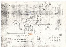
Hi. I'm in London till summer and my good old proven schematic is at my home. In paper form. I will try to ask someone to take photo of it. I have p-cad pcb file for such psu...
But of course you can google it. LM723. It is maybe a little hard to find schematic with both current and voltage adjustment. Mine psu uses only one ic and big darlington output transistor some passive components and 2 pots for I and U reg. There is no other ic.
Cheers, Taj
But of course you can google it. LM723. It is maybe a little hard to find schematic with both current and voltage adjustment. Mine psu uses only one ic and big darlington output transistor some passive components and 2 pots for I and U reg. There is no other ic.
Cheers, Taj
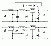
Lm2596 + 317 2596 + 337
I have 2 options for you, basic minimum components, I used the Ebay 2596 board with current regulator and the 317 /337
use for the LM 2596 a stereo potmeter 10K with about 1,2 Kohm in series to create the 4-5 Volts tracking offset and the second 10Kohm potmeter for the LM317.
Done
use a 2596 in series with a LM337
see enclosed basic diagram add C and protection diodes to the 337 as required
R= 1,2k, 100k, 3,9k for 5V offset, 10k pot + 390ohm
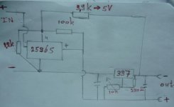
The simplest thing to do is simply use a dual pot. The LM2596 will be very unstable otherwise. I have sketched one possible circuit but it will take some experimentation to determine circuit values. You will probably burn up some parts in the process.
I tried your diagram with a TIP 42 5V zener 50 ohm resister in series (but I expect this resistor is not needed) and the 2596 tracks nicely with about 6 volts over te output voltage of the 317 ( 338 I do not have) I used both 2596 and 317 standard little boards from ebay and left all the original parts in place.
TX man great job
- Status
- Not open for further replies.
- Home
- Amplifiers
- Power Supplies
- Adjustable 0-24V 1A bench PSU