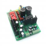
I ordered two SMPS off eBay, pictured as below. They are labeled as +/-30v, but the actual output under 10ma current load is +/-39v and +/-33v. I have emailed the seller but got no answer so far. I'd like to find a way to adjust the output voltages, maybe by changing some resistors? Any one is familiar with this particular model?
Thanks!
Thanks!
Attachments
Load it up with a more reasonable load and you might find it works as expected. I have a 280V supply that reads 395V with such a small load 🙂
I have three other SMPS of the same model. Two 35v ones are used in a Pass A5 amp with 250w quiescent, one 70v in P7 preamp. The full load voltage drops are all < 1v compared to no load. So don't think 1A load will make much difference for them, but will confirm.
1A is 100 times as much as 10mA, a significant difference.So don't think 1A load will make much difference for them
Your supply might want to see, say, 20-30-50 mA minimum load before regulating to proper voltage.
Here is some test result:
10ma : 33.5v
250ma: 33.3v
As my experiences with this SMPS in class A power amp application, 2A constant current load will only drop < 1v.
10ma : 33.5v
250ma: 33.3v
As my experiences with this SMPS in class A power amp application, 2A constant current load will only drop < 1v.
Any one is familiar with this particular model?
Which is.... what?
Maybe:
PCB for Shunt Regulated Dual Voltage Power Supply Preamplifier Headphone Amp for sale online | eBay
... labeled as +/-30v, but .... +/-39v and +/-33v. ...
"Item not as described. Refund!"
Yeah, the seller did refund today.
Now trying to figure out what to do with this SMPS. Don't know much about it, but want to trash it just yet.
Now trying to figure out what to do with this SMPS. Don't know much about it, but want to trash it just yet.
Get an amplifier that is comfortable with +/- 39 V and another one for +/- 33 V 😀.
Or do some reverse engineering. Most PWM controllers provide a reference voltage of 2.5 V. So you just need to identify and modify the output voltage divider(s).
Best regards!
Or do some reverse engineering. Most PWM controllers provide a reference voltage of 2.5 V. So you just need to identify and modify the output voltage divider(s).
Best regards!
Its usually just a resistor change in a voltage divider to set output voltage.
Unless its a no feedback model in which case your stuck with what ever transformer puts out.
Unless its a no feedback model in which case your stuck with what ever transformer puts out.
No optocouple in sight along the isolation barrier: This is an unregulated supply imho. No idea how to tune the output voltage.
The only way is to adjust the transformer windings.
Try removing one turn from the secondary to reduce the voltage.
Try removing one turn from the secondary to reduce the voltage.
This kind of SMPS are quite different from the ones I tinkered before, it contains only one integrated module with five resistors, 1.4M x 1, 12K x 2 and 210 x 2, no other ICs. Don't think the resistors are of different values for boards of different output voltage. Figure it is quite hard get accurate transformer ratio, just don't know it that well.
I'd like to find a way to adjust the output voltages, maybe by changing some resistors?
There appears to be a difference in the value of the surface mount resistors on the back of these boards for different output voltages. The 55V units appear to use 100R. What is the value on yours?
I've bought one of these boards and would also be interested to know.
Last edited:
My 30v rated has R025. That is interesting, maybe I can test different resistor, it can also through hole.
I now have a 40V and 45V version of this supply. The SMD resistor on the back is the same value in each. I measured the secondary windings and can confirm the DCR is different and it appears the only difference between these two supplies is the transformer. Nigel was right on the money a few posts up. All other components in my two supplies are identical.
Fly back SMPS are more flexible on voltage than LLC.
They are usually made to work wit ha wide range of mains voltages.
And the transformer ratio isnt as important as its passing charge rather than simple transforming. They use feedback to set output voltage.
I think in your case you have LLC SMPS which rely on transformer turns to set the voltage. They can be set to regulate a bit with feedback but not a massive range like flyback.
Switching supplies should be stable without a load. This isn't the early 1980s anymore. That is cheap garbage that I would not leave unattended.
These supplies are stable without load. Their regulation is actually pretty good considering they don't use feedback. The output drops by only a couple of volts between no load and full load. I didn't test it but I assume line regulation is poor.
I have this power supply.
I ordered a 2x37V, but there is 2x41V in true.. Not a big problem but the seller don't give me good solution. No refund, no explain, just tell me to add more load in the output 😀
Somebody here has tested the real power (with a big load)? because I know that 500w is ... unreal, but what is the real power ?
- Home
- Amplifiers
- Power Supplies
- Adjust SMPS output voltage