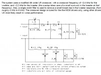
I was reviewing crossovers for a two-way system design and remembered this crossover for the Adire Audio Bang project from a long time ago. I am using it as a starting point to reacquaint myself with the practical implementation of crossover networks.
A bit rusty but, I have a basic understanding of the Linkwitz crossovers and compensation networks. Trying to understand this modified design because it seems different.
Let's start with the tweeter, and what I think I think understand about the circuit:
Normally, I would simulate this in LTSpice, but can't get it to install on my machine and I'm little strapped for time for a complete analysis at the moment. Just trying to understand basically what's happening. Any input would be appreciated.
A bit rusty but, I have a basic understanding of the Linkwitz crossovers and compensation networks. Trying to understand this modified design because it seems different.
Let's start with the tweeter, and what I think I think understand about the circuit:
- First parallel RLC, I am assuming is the notch filter to flatten the tweeter response as mentioned.
- If the other resistors are removed, it would appear that the remaining LCs form the classic 4th order L-R filter.
- If the two statements above are correct, then what are the roles of the other resistors? Was thinking L pad, but that does not look right. Basic resistive compensation?
Normally, I would simulate this in LTSpice, but can't get it to install on my machine and I'm little strapped for time for a complete analysis at the moment. Just trying to understand basically what's happening. Any input would be appreciated.
Attachments
Last edited:
 Like this 🙂
How to attach images to your posts.
I'm also going to delete the links you posted because they run to ten's of thousands of characters as you can see here, and that can screw up page loading.
Attachments

- Status
- Not open for further replies.