The application is DC LED power supply for motorcycles with an AC electrical system.
I came across this video https://www.youtube.com/watch?v=3qHJFvjwkI4
which presents the attached diagram.
My question is about the single forward-biased diode after the bridge rectifier positive terminal. At first blush, I though perhaps the author didn't understand what a bridge was, as of course there are 2 forward-biased diodes attached to that positive terminal in the bridge rectifier.
Then I thought perhaps there was some merit I could not see because of this specific application. The fact that only of 1 of the 2 forward-biased diodes inside the bridge conducts on each half of the AC wave, perhaps significant when driven by a stator? The fact that the AC input voltage is continuously fluctuating with RPM?
What's the verdict, yay or nay?
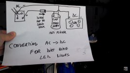
Attachments
My question is about the single forward-biased diode after the bridge rectifier positive terminal.
There's no reason for it. He doesn't understand how a bridge rectifier works.
Last edited:
One application for a diode after a power supply is when you are making a redundant system. The diode isolates the two supplies at the cost of a 700mv drop.
> He doesn't understand how...
+1.
I don't even know what it means "drain back". Maybe he is confused with a battery charger. Even so the bridge would do it.
I did the same on a cheap snowblower, had a glove-box lamp as a "head light". Got a hot ATV light off Amazon, got a Bridge from Radio Shack (my last trip before they folded). I didn't even bother with the cap. It flickers, but that don't bother me when blowing, and does alert the oncoming cars "something strange here!"
People nowadays often seem to add redundant diodes to circuits, then come up with a fanciful 'explanation' about what they do. I guess it just shows how cheap diodes are, and how confused some people are.
Maybe to reduce the voltage fed to the cap and LED.
I don't see any current limiter for the LED and maybe it blows up when the full voltage is fed into it.
I don't see any current limiter for the LED and maybe it blows up when the full voltage is fed into it.
the diode is there so that the led still lights up for a time even after the bike has come to a full stop...i think that was the intention...
maybe there are other loads fed from the bridge which make the diode have some sense...
maybe there are other loads fed from the bridge which make the diode have some sense...
It will do that without the extra diode, it is in series with the four diodes in the rectifier.
Except for the voltage drop across the diode, it makes a cheap fuse.
Except for the voltage drop across the diode, it makes a cheap fuse.
Maybe he had in mind the DC dynamos in very old vehicles which indeed required something that isolates the battery from the dynamo when the engine was operating at too low rpm or not operasting at all. Contemporarily this was done by a relay inside the governor, but might as well have been power diodes if these were available about 50 years ago. Besides this, the diode in the depicted application might separate the anti-flicker cap from the load presented by the vehicle's electrical system.
Best regards!
Best regards!
It could be that the circuit shown to us is not the complete circuit, but that is a different issue.
Maybe he had in mind the DC dynamos in very old vehicles which indeed required something that isolates the battery from the dynamo when the engine was operating at too low rpm or not operasting at all.
But that is already done with the diodes in the bridge, so here that diode is useless.
Besides this, the diode in the depicted application might separate the anti-flicker cap from the load presented by the vehicle's electrical system.
But for that the diode is in the wrong position, so here that diode is useless.
Jan
- Status
- Not open for further replies.
- Home
- Amplifiers
- Power Supplies
- Additional diode after bridge rectifier?