I have used a similar circuit to simulate a "superconductive loudspeaker coil", a form of implicit MFB. I didn't have stability problems (except when I went too close to the "superconductivity" limit).
The most annoying effect (from my perspective) was the variation of apparent gain with the simulated impedance setting. But if you use this circuit within more reasonnable limits than I did, this shouldn't be too much of a problem.
can't find settings that fit 🙁
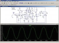
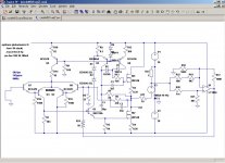
Running a transient analysis on different pot positions – results are quite exciting ! - well, for any effect gear – but no exactly what I was after 🙂


Could you share your schematic - or correct mine ?
what you mean with :
"The most annoying effect (from my perspective) was the variation of apparent gain with the simulated impedance setting."
Michael
Last edited:
A fully variable, continuous controller providing any impedance from +z to -z.
We have a couple amplifiers here -- variable tranconductance amp -- that have a pot on the front that causes output impedance to go from close to 0 to practically infinity. Made by Duo (aka Daniel). I've pinged him.
dave
can't find settings that fit 🙁
Running a transient analysis on different pot positions – results are quite exciting ! - well, for any effect gear – but no exactly what I was after 🙂
Could you share your schematic - or correct mine ?
Michael
I don't see where the problem is: you just have to connect the circuit to any old conventional amplifier, and it works: look at the example.
If you try it on other architecture, or you cascade multiple stages, or you add a pole in the response with an RC circuit, you might get into problems (you get into problems in fact).
In the example, a positive output impedance is simulated; this can be changed by altering the R20 to R22 ratio.
When the simulated negative impedance is close to the copper resistance of the loudspeaker coil, the output level becomes huge, because it simulates a speaker having an ideal efficiency.what you mean with :
"The most annoying effect (from my perspective) was the variation of apparent gain with the simulated impedance setting."
Conversely, if you simulate a +10ohm output impedance, it's exactly like you insert a 10ohm in the output: the loaded level is reduced accordingly.
Attachments
Hello,
My work would not really be appropriate to your request mige0 but it is similar.
I develop amplifiers with this technology incorporated within the feedback loop. To wrap it around the outside of an existing amplifier is possible but you run into a few problems. The main problem is stability. Too much feedback and the whole system will oscillate.
It it still worth a try. It is even possible to make it fully adjustable on the fly (which is what I've done in my stuff).
Thanks Planat10, Elvee and Duo.
I've found the fault being in the LT1007 I used without checking further.
I replaced with a instrumentation amp and everything is fine.

Regarding my low pass filter (R12 / C1) its actually beneficial for stability - without it, 180 deg of phase shift may or may not be reached at 0dB - depending on the power amp's Bode diagram.
With the low pass filter in place I gain a comfortable phase reserve.
Duo - is the circuit you use any similar to mine or Elvee's ? Could you possibly share a schematic ?
Michael
I've found the fault being in the LT1007 I used without checking further.
I replaced with a instrumentation amp and everything is fine.
Regarding my low pass filter (R12 / C1) its actually beneficial for stability - without it, 180 deg of phase shift may or may not be reached at 0dB - depending on the power amp's Bode diagram.
With the low pass filter in place I gain a comfortable phase reserve.
Duo - is the circuit you use any similar to mine or Elvee's ? Could you possibly share a schematic ?
Michael
I'm not exactly interested in negative impedance (the opposite actually) - but as there are so many here that have first hand experience with such a tool I have a question or two.
Not having thought a lot about it, I have a feeling that a simple circuit can not *really* compensate ?
I mean - you would have to model the complex impedance of the speaker in question - no ?
So in end effect mid frequencies - where impedance is lowest - will be raised overly - no ?
Michael
Not having thought a lot about it, I have a feeling that a simple circuit can not *really* compensate ?
I mean - you would have to model the complex impedance of the speaker in question - no ?
So in end effect mid frequencies - where impedance is lowest - will be raised overly - no ?
Michael
It compensates for what it is set to compensate: in my case, I wanted to get rid of the copper resistance, ie. the DC resistance you see with an ohmmeter. I even made the shunt resistor from thin copper wire, in order to compensate for thermal effects. But I took care to make a non-inductive winding, as I didn't want any other effect to interfere.
But there is no theoretical objection to compensating other effects: reactive elements could be inserted in the feedback path. It depends on your goal. But obviously, with reactive elements, guaranteing stability could become tricky.
But there is no theoretical objection to compensating other effects: reactive elements could be inserted in the feedback path. It depends on your goal. But obviously, with reactive elements, guaranteing stability could become tricky.
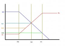
actually if you raise the output impedance of the amp, it's only going to have an effect below the frequency limited response of the amp's feedback (usually about 100hz to 1khz, depending on the amp). above the feedback turnover frequency the output impedance rises until it's equal to the amp's output resistance (at the amp's bandwith limit) as the effective feedback decreases. the raised output impedance will turn over at a higher frequency.
in the chart below, you see the Aol curve (standard Bode plot), and where the closed loop intercept is (Acl). also plotted is the output impedance curve (Zo). beginning at the open loop turnover frequency (Fol), Zo begins rising. if we were to set the output impedance at a higher level, it intercepts the Zo curve at a higher frequency. at the GBW limit of the amplifier (F1) Zo=Ro (the "raw" output resistance of the amplifier).
Acl does have an effect on Zo, because Zo (below Fol) is approximately Ro/(Aol/Acl)...(i'm pretty sure this is a close approximation. if it's in error, let me know)
Attachments
Last edited:
... I even made the shunt resistor from thin copper wire, in order to compensate for thermal effects. ...
An interesting approach ! which where your findings ?
Michael
uncl ejed613;2068813 said:actually if you raise the output impedance of the amp, it's only going to have an effect below the frequency limited response of the amp's feedback (usually about 100hz to 1khz, depending on the amp). ....
Not sure if it counts for "old school" solide state amps.
I mean - they are so low in output impedance that my guess would be that even at the top audio band they do not exceed a few Ohm.
As I want to rise Qts of bass speakers to values that are good for open baffle application, I think I need somewhere around 30 - 80 Ohm output impedance *below* ~ 100Hz to reach my goal with the vast majority of bass drivers available.
Bottom line - I think you are right in theory, but on the other hand I'm not bothered for the application I'm after.
Michael
Last edited:
you could do it with a transformer AND an impedance controller. a 1:2 turns ratio toroid would probably be "the ticket". since it's for bass, an AC power transformer would probably work surprisingly well. if you have any power amp PS transformers, use half of a 50-0-50 secondary as the load on the amp, and the 120V side to feed the speakers.
Possibly - but I want to set effective Qts *precisely* by being able to accurately control output impedance
Michael
Michael
using a transformer will transfer the effects of a variable impedance controller through the mutual inductance, so you will still have control over it.
My circuit involves taking two feedback nodes from the amplifier output and taking a sum of those to the inverting input. This then comprises the entire feedback loop for the amplifier.
A voltage node is simply provided by a resistor divider across the load (must be referenced to the same place as the inverting input is referenced to (usually signal ground)).
The current node is provided via current shunt in series with the load. Best on the ground side otherwise you need a differential amplifier just to look at the current sense resistor. (This would be ideal, but is more complex.)
Some sort of variable or static mix from these to nodes is taken. In the most rudimentary of my designs I've use a potentiometer to do this. Beware that the pot will load the nodes via each other and if you pick a pot value too high to mitigate this effect, you'll have a peak in the gain as the pot approaches mid-travel. There are elegant ways of working around this and eliminating the pot altogether, but I will not get into that here.
The wiper of the pot can go to the amplifier's inverting input, and again, if the impedance of this input is too low, the gain-peak mentioned before will be excessive and the desired effect will be overshadowed if you're trying to tune by ear.
Everything I'm talking about can be found on Rod Elliot's website almost verbatim.
Variable Amplifier Impedance
You can use the circuit in Figure. 2 to accomplish a desired Qts very easily. If you want to use the around an existing amplifier, it can be adapted.
I assume all this has already been covered by those in this thread and migeo: you're familiar with all of it?
Anything I have done myself is just a much more advanced approach to accomplishing the same thing but doing it better (smooth transition between low/high impedance, a switch to select known speaker impedance to program the amp to maintain a more constant gain, pot-less electronic control of Zo, etc etc).
Glad to help if I can.
I think in your situation it's either A: Modify the amplifer. or B: design a feedback loop to go around the outside. Both are doing the same thing, just one has a bit of redundancy going on.
I think in your situation it's either A: Modify the amplifer. or B: design a feedback loop to go around the outside. Both are doing the same thing, just one has a bit of redundancy going on.
Doesn't it sounds logic, wether wanting to distribute two kinds of feedback, to be able to attenuate the first one prior to apply the second one?
B makes it impossible.
B makes it impossible.
B leaves the possibility of adjustment, but leaves the internal feedback loop alone which is why I mentioned redundancy. This is not as desirable as option A in which you can pick each feedback loop as a percentage of the total. The total sets the gain, which for a known resistance will cause a change in gain during Zo adjustment if the two nodes are scaled for some other resistance.
For example, in my adjustable amplifier, I've scaled the nodes for 8 ohm loads. For most cases this gives the effect of apparent gain staying the same (sound volume), and the damping factor changing. If I attach 4 ohm speakers, a dramatic gain-change occurs since for the same voltage, there will be twice the current not considering reactance in the load.
This is not of paramount importance, but is an issue you encounter when doing this.
Last edited:
Glad to help if I can.
I think in your situation it's either A: Modify the amplifer. or B: design a feedback loop to go around the outside. Both are doing the same thing, just one has a bit of redundancy going on.
Yes, it really helps to have someone here with first hand experience on such circuits - I am "familiar" with the topic only from theory (and my simus) - so actually I'm not familiar at all !
😉
Regarding wrapping around versus modding an amp - I already have modded amps I'm happy with. I think many people are even in the situation not being able to mod - so modding isn't an option as I intend to do something that is widely applicable (well in far future....)
In particular, you are confronted with the stability problem anyway. At a first glance, I could increase low pass even up to 1-10kHz with "usual" amps.
Keeping LP at ~ 100Hz seem to provide a comfortable margin.
I agree tho, that wrapping a feedback loop around a existing amp - like I intend to do - increases the risk to end up with too low phase margin due to the additional (instrumentation) amp needed.
On the other hand, the power amp itself is already stable - there is no change in this - and I "only" have to stay clear that the additional circuit stays stable as well.
So I have to check out and model the Bode diagram of my amp for sure.
###
This I think I didn't fully understand:
" and again, if the impedance of this input is too low, the gain-peak mentioned before will be excessive"
Michael
The gain-peak thing if specific to my circuit in which I use a potentiometer to vary between the voltage and current nodes.
If the resistance of the pot is too low then the nodes affect each other too much and there's little variance for amplifier output impedance. If the pot resistance is too high, then the input of the amp loads it too much and the gain changes drastically, all else (like load resistance) being equal.
In my current designs I use a jfet input diffamp to keep the load impedance on the pot high enough to make this effect more or less go away. The capacitance of this input must also be considered as it can of course cause an uneven frequency response, but this is true of a normal voltage feedback loop too.
- Status
- Not open for further replies.
- Home
- Amplifiers
- Solid State
- Adding Variable Impedance to Power Amp