Hi, Could anyone recommend where I should install a trimpot to adjust the current on the output transistors on a pioneer sx-434, cutting the wires as per service manual is not very accurate. I know the picture is not very clear but it is all I have, thanks in advance, Happy Christmas to all.
Attachments
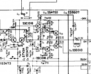
I can't see the designation numbers of the components because of the picture quality, but it looks like there is a 10ohm resistor with a link over it that is probably the wire the manual refer to?
I guess putting in a trimmer of a low value (20ohm?) instead of that resistor would give you some adjustment.
Others please correct me if I'm wrong.
I guess putting in a trimmer of a low value (20ohm?) instead of that resistor would give you some adjustment.
Others please correct me if I'm wrong.
please check out the idle current with and without the 10R short wire (value of voltage across the emitter resistors from the output buffer). Dependent of this value we can say the next step. The best value is 20-25 mA after switch-on one hour.
Maybe it is possible to replace the wire by a variable resistor between 50R and 100R and after obtain the correct idle current it is the best to measure and replace the variable resistor by a non variable version (this I do always in the last years and it will no longer occur unwanted drift effects cause contact issues on the potentiometer resp. variable resistor.
Another approach is the replace of D2-4, R72 and R70 by a complete Vbe multiplier (the good known circuit topology) consist of a small/medium signal transistor for mounting on the main heat sink for the output devices so as two resistors and a variable resistor (maybe a spindle trimmer).
This is a good sounded device - go to
SX-434 - Pioneer SX-434 - Audiofanzine
My brother use it in a second set up.
For the ps caps he use the Mundorf caps
Netzteil Kondensatoren - Mundorf EB GmbH
Last edited:
Ok fair point about using a fixed resistor, as long as other components do not drift over the years, I would usually install a multi turn trim pot, Yes that is a 10 ohm resistor with a wire jumper, I had a blown channel and decided to replace all 4 output transistors, all electrolytic caps and all pre-drivers, including some new transistors on the pre amp section, I will measure what I have first and report back. I have not had time to measure yet, still running on lamp / current limiter for now, first impressions is it sound very good indeed, the FM tuning is also really good (tuner also recapped, small caps with film)
Have a look thru this thread: Adjusting the DC Offset in SX-434 | Audiokarma Home Audio Stereo Discussion Forums
jeff
jeff
Pioneer used fixed resistors there for a reason.
Because if a pot was used, and it opened up, the outputs would fry.
The use of a small value pot in place of the jumper might be safe.
Because if a pot was used, and it opened up, the outputs would fry.
The use of a small value pot in place of the jumper might be safe.
Ok I snipped the jumper wire marked D on the service manual jumping the resistor and it has brought the 60mV down to 6mV on power up and rising to about 12mV after a few minutes, with the 8 ohm load resistors /dummy on the speaker terminals, I will leave it powered up for an hour before checking the bias again off the current limitor, but looks a lot better all ready. I used TIP41 and TIP42 as replacement output transistors it is what I had in stock. I will leave off the idea of the trim pot so. Thanks for all the advise. Great receiver with some old philips 22rh427 speakers
- Home
- Amplifiers
- Solid State
- Adding trimpot for bias control on pioneer SX-434