Hi,
I am building a replica for a Marshall 18W. The guy wants the TMB channel, with an active FX Loop and a Reverb effect. For the FX loop, I'm using a kit from Tube Town. It works quite straight forward.
The issue is that when I'm trying to plug the Reverb circuit, it does not work properly. As you can see in the circuit, I am taking the signal from the Master, then I use the Phase Inverter to mix the signals.
What am I missing here?
Any help will be very much appreciated
Attachments
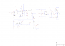
The phase splitter will not work correctly unless the grid of the lower portion is not grounded through the capacitor. The second half of the phase splitter must be allowed to use its cathode to modulate the anode, not the grid.
Take your feed from the wiper of the treble control and feed the output of the reverb unit on the top of the master volume control.
Take your feed from the wiper of the treble control and feed the output of the reverb unit on the top of the master volume control.

The phase splitter will not work correctly unless the grid of the lower portion is not grounded through the capacitor. The second half of the phase splitter must be allowed to use its cathode to modulate the anode, not the grid.
Take your feed from the wiper of the treble control and feed the output of the reverb unit on the top of the master volume control.
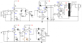
I kind of disagree with the capacitor that you are talking about. Here is the circuit for the Marshall 18W TMB. Plus I tried (without the Reverb) and it works properly.
I will check this idea of putting the Reverb between the Treble and the Master
Thanks
Attachments
As I said, the phase splitter does not work correctly. It is unbalanced due to modulation on the lower grid, the same with the Vox.
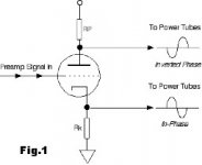
This type of phase splitter is not the best but cheap to make as it has good voltage drive.
This type of splitter is called a long tail phase splitter. Diagramme on the left.
This type of phase splitter is not the best but cheap to make as it has good voltage drive.
This type of splitter is called a long tail phase splitter. Diagramme on the left.
Attachments

You are right, I am familiar with the circuit that you posted. I will try it in any case. I was also reading in a different page that the Reverb circuit that I'm using needs at least 3 stage of amplification. The thing is that when I do that, I saturate very quickly the output stage. I'll check in a while, and keep you posted.
Thank for the help
Thank for the help
Is this a hifi amplifier or a guitar amp? Odd that all the Vox's in history that use this circuit are trash. Same with all the 18 Watt amps that use the two inputs, not to forget Matchless. I am sure there are many others that are 'wrong' that are well thought of.
...does not work properly. ...
What does it do? Catch fire? Scream like a dog with his tail in the door? Convert blues into polka?
The "other side" of the long-tail *can* be an effective second input and mixer.
The likely problem is that it is not wired as-drawn.
Oh... and the reverb recovery amp is upside down so all the sound falls out...
Well, the issue is that I do not hear the Reverb effect at all. When I press the footswitch the sound becomes slightly saturated.
I checked the wire and it is OK. Except that the Reverb transformer was wrongly connected (BLUE cable to B2 and the RED to the Anode). I inverted, but maybe I ruined the transformer. I have another one, so I'll try it tonight.
Any chance of making the schematic more readable? Can't see some of the values.
It's readable, if you expand then expand again and scroll-pan-scroll around. It's like 30000x2000 pixels, far larger than my display. The value text is drawn 1 pixel line-width, a zero is 7x5 pixels. On my monitor it is impossible to see the whole thing and also read values. Can't read them at half-size, because half of one pixel can be nothing at all.
When I press the footswitch...
I don't see any footswitch, at the usual place or anywhere in the reverb path.
OK I got it (picture size). First off, you don't need 220k R17, that is a mixing resistor in Fender's circuit, you are doing no mixing. I would have the triode center biased with a 1.5k rather than a 820R. I noticed the tail resistor in the PI is 22k, that seems pretty low for a 18 Watt, normally around 47k, 56k, not that it would have any bearing on the reverb problem. First thing I would do is check the output to the tank. Disconnect it and feed it to a speaker. It should sound like a bassless 2-3W amp. If that sounds ok then move on to the input from the tank. Feed a signal into it. it should give you some sound. If not, disconnect R17 and jumper the pot to the other side of the LTP. If it works then that section works. Troubleshooting is just a matter of eliminating things that work. Sometimes things can work but not work together, those are a little harder to figure out.
Last edited:
OK I got it (picture size). First off, you don't need 220k R17, that is a mixing resistor in Fender's circuit, you are doing no mixing. I would have the triode center biased with a 1.5k rather than a 820R. I noticed the tail resistor in the PI is 22k, that seems pretty low for a 18 Watt, normally around 47k, 56k, not that it would have any bearing on the reverb problem. First thing I would do is check the output to the tank. Disconnect it and feed it to a speaker. It should sound like a bassless 2-3W amp. If that sounds ok then move on to the input from the tank. Feed a signal into it. it should give you some sound. If not, disconnect R17 and jumper the pot to the other side of the LTP. If it works then that section works. Troubleshooting is just a matter of eliminating things that work. Sometimes things can work but not work together, those are a little harder to figure out.
Thank for the tip. I measured the signal at the tank (4AB3C1B) output and it was 0V. I changed for a 8AB2A1B, and now it works properly. The Reverb Transformer that I am using is a Hammond 125A20B / 022921. I am not sure if the tank is defective.
Also, instead of taking the signal from the Master, I took it from the Cathode Inverter. I also removed the 22k. I will have a look to the LTP
- Status
- Not open for further replies.
- Home
- Live Sound
- Instruments and Amps
- Adding Reverb to Marshall Replica TMB 18W