Hi everyone,
I wish to add an headphone output to John's Broskie Aikido LV PCB which unfortunately lack one.
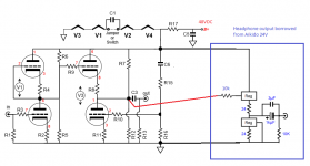
Since I couldn't a similar project featuring one, I had the idea to borrow the headphone driving section from Aikido 24V schematic and "paste it" to Aikido LV schematic since they seems similar to me. (The two parts identified "Reg" are LM317/LM350/LT1085 etc.)
Would it work ? Is there any better alternatives ? (I'm using 48V B+ & 12BH7 valves and I'd like to drive a wide range of headphone impedance (32-600 ohms))
Thanks a lot for your help and suggestions !
I wish to add an headphone output to John's Broskie Aikido LV PCB which unfortunately lack one.
Since I couldn't a similar project featuring one, I had the idea to borrow the headphone driving section from Aikido 24V schematic and "paste it" to Aikido LV schematic since they seems similar to me. (The two parts identified "Reg" are LM317/LM350/LT1085 etc.)
Would it work ? Is there any better alternatives ? (I'm using 48V B+ & 12BH7 valves and I'd like to drive a wide range of headphone impedance (32-600 ohms))
Thanks a lot for your help and suggestions !
Attachments
Last edited:
What's the output impedance of your preamp with 12BH7s?
You might just want to try a 470uf cap as the output coupling capacitor and see if that will get loud enough. The challenges you have to overcome are the high pass filter created by the coupling cap and the low impedance load of the headphones.
The high pass part is fairly easy:
C = 1 / 2 * Pi * Z * f
where C is the cap value in farads, Z is the headphone impedance, and f is the -3db frequency point. A 470uf cap gives you a -3db point at about 10hz.
The low impedance load part is not so straightforward. There are two major issues:
1. if the output impedance of the amp is high, the damping factor will suffer (leads to mushy bass)
2. if the output impedance of the amp is high, you'll also have poor power transfer
Now as far as #2 goes, you don't need much power for headphones. As far as #1 goes, you'd need a way to lower the output impedance (this will also help #2). That could be done with solid state buffering assistance, transformer coupling, or tube follower assistance. Tube followers can't really get low enough practically if you want to use 32 ohm headphones. Transformers are hard to find with the right ratios. Solid state is cheap but doesn't like tube B+ voltages.
IIRC, the low voltage Aikidos use a voltage multiplier, don't they? I think even if your B+ is truly 48V, you're going to be pretty close to the voltage limits of the LM317/LD1085. Note this part of Broskie's write-up:
I'd investigate along these lines maybe with a IRF510 as the MOSFET. You'll want to make sure everything is on a heatsink (though it shouldn't need to be gigantic). You'll also still end up with a big fat electrolytic on the output.
You might just want to try a 470uf cap as the output coupling capacitor and see if that will get loud enough. The challenges you have to overcome are the high pass filter created by the coupling cap and the low impedance load of the headphones.
The high pass part is fairly easy:
C = 1 / 2 * Pi * Z * f
where C is the cap value in farads, Z is the headphone impedance, and f is the -3db frequency point. A 470uf cap gives you a -3db point at about 10hz.
The low impedance load part is not so straightforward. There are two major issues:
1. if the output impedance of the amp is high, the damping factor will suffer (leads to mushy bass)
2. if the output impedance of the amp is high, you'll also have poor power transfer
Now as far as #2 goes, you don't need much power for headphones. As far as #1 goes, you'd need a way to lower the output impedance (this will also help #2). That could be done with solid state buffering assistance, transformer coupling, or tube follower assistance. Tube followers can't really get low enough practically if you want to use 32 ohm headphones. Transformers are hard to find with the right ratios. Solid state is cheap but doesn't like tube B+ voltages.
IIRC, the low voltage Aikidos use a voltage multiplier, don't they? I think even if your B+ is truly 48V, you're going to be pretty close to the voltage limits of the LM317/LD1085. Note this part of Broskie's write-up:
The IXCY10M45S, on the other hand, is a high-voltage device. Thus the bottom regulator can be replaced with a IXCY10M45S and the top regulator, any high-voltage, low-wattage, N-channel MOSFET that can be had in the TO-220 package.
I'd investigate along these lines maybe with a IRF510 as the MOSFET. You'll want to make sure everything is on a heatsink (though it shouldn't need to be gigantic). You'll also still end up with a big fat electrolytic on the output.
Last edited:
Thank you very much for your reply,
According to the manual, output Z is calculated as the following
To the best of my knowledge, that should give (assuming rp being Plate Resistance and mu being amplification factor)
Zo = [5300/(16.5+1) + 249] || [1 000 000] || [5300 + (16.5 + 1) 249]
Zo = 551.8 || 1 000 000 || 9657.5
Zo = 521 ohms
Does that make sense ? Is it considered low or high output Z ?
Great ! But let's say I wish a more "universal" option that is not customized for one headphone impedance in particular?
That's one of the main reason I went with a 48VDC B+. Voltage is much more manageable.
If my memory serves me right, there's a 12VAC Aikido PCB which incorporates a voltage doubler but it's not my case.
The heater string and B+ are fed from the same 48VDC supply.
You're right, 48VDC would exceed previously mentionned regulator max voltage. However, there is LM317HV which can go up to 57VDC.
Assuming LM317HV can withstand a 48VDC B+, would the provided schematic in the original post work ?
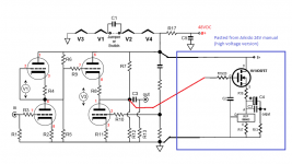
Would the attached schematic work ?
Finally is there any advantages to use the IXCY10M45S/IRF510 approach VS the LM317HV/LM317HV one considering relatively low B+ voltage ?
Thanks again !
What's the output impedance of your preamp with 12BH7s?
According to the manual, output Z is calculated as the following
Zo = [rp/(mu +1) + R8] || R13 || [rp + (mu + 1)Rk] where “||” stands for in “parallel with.”
To the best of my knowledge, that should give (assuming rp being Plate Resistance and mu being amplification factor)
Zo = [5300/(16.5+1) + 249] || [1 000 000] || [5300 + (16.5 + 1) 249]
Zo = 551.8 || 1 000 000 || 9657.5
Zo = 521 ohms
Does that make sense ? Is it considered low or high output Z ?
The high pass part is fairly easy:
C = 1 / 2 * Pi * Z * f
where C is the cap value in farads, Z is the headphone impedance, and f is the -3db frequency point. A 470uf cap gives you a -3db point at about 10hz.
Great ! But let's say I wish a more "universal" option that is not customized for one headphone impedance in particular?
Transformers are hard to find with the right ratios. Solid state is cheap but doesn't like tube B+ voltages.
That's one of the main reason I went with a 48VDC B+. Voltage is much more manageable.
IIRC, the low voltage Aikidos use a voltage multiplier, don't they? I think even if your B+ is truly 48V, you're going to be pretty close to the voltage limits of the LM317/LD1085
If my memory serves me right, there's a 12VAC Aikido PCB which incorporates a voltage doubler but it's not my case.
The heater string and B+ are fed from the same 48VDC supply.
You're right, 48VDC would exceed previously mentionned regulator max voltage. However, there is LM317HV which can go up to 57VDC.
Assuming LM317HV can withstand a 48VDC B+, would the provided schematic in the original post work ?
I'd investigate along these lines maybe with a IRF510 as the MOSFET. You'll want to make sure everything is on a heatsink (though it shouldn't need to be gigantic). You'll also still end up with a big fat electrolytic on the output.
Would the attached schematic work ?
Finally is there any advantages to use the IXCY10M45S/IRF510 approach VS the LM317HV/LM317HV one considering relatively low B+ voltage ?
Thanks again !
Attachments
Does that make sense ? Is it considered low or high output Z ?
Yes, that sounds about right. For a preamp that would be a low output impedance; for a headphone amp it's very high. You'll want to do something to lower it (like JB's suggestion of regulators/MOSFETs).
Great ! But let's say I wish a more "universal" option that is not customized for one headphone impedance in particular?
32 ohms is about as low impedance as headphones get in most cases. Anything higher in impedance will actually push the -3db point lower (so it would work fine with the same cap).
Assuming LM317HV can withstand a 48VDC B+, would the provided schematic in the original post work ?
The B+ is going to be divided between the two regulators, so this might work ok if the B+ is only 48V. Your output voltage isn't going to swing that much in AC terms.
Finally is there any advantages to use the IXCY10M45S/IRF510 approach VS the LM317HV/LM317HV one considering relatively low B+ voltage ?
Just peace of mind, really. It's good practice to always leave lots of leeway in terms of voltage and wattage ratings. The LNM317HV would probably work fine, but if you suddenly fry them one day, you'll curse the fact that you didn't spend an extra buck for the 10M45S instead.
Thank you very much !
Is it me or you would build a completely different headphone output ? 🙂
You'll also still end up with a big fat electrolytic on the output.
Is it me or you would build a completely different headphone output ? 🙂
Haha. Every approach is going to have some kind of tradeoff. OTL usually has a big cap in the output, transformers lessen or eliminate it but they have their own issues (and are usually pricier).
If you already have the Aikido, I'd see how far you can take it with just the SS and cap output. Broskie has one hundred and one options that you can always try later.
If you already have the Aikido, I'd see how far you can take it with just the SS and cap output. Broskie has one hundred and one options that you can always try later.
- Status
- Not open for further replies.