Hi,
I was hoping someone could tell me if I have done this right please?
I have made the caps and snubber section (less 1 cap) of the carlosfm power supply from here...
http://myweb.tiscali.co.uk/nuukspot/decdun/gc/snubberedPSU3.png
And I want to put it between the power and amp boards of my rev3 LM3875 kit.
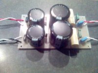
As I'm connecting from the existing power board I have +V, 0 and -V, 0. I have connected the caps like this + to +V, and - to 0 and - to -V and + to 0.
I'm pretty sure this is right because all I'm doing is running 2 seperate 0's but wanted to check as I don't fancy being anywhere near a 10,000 uF cap if it explodes!
I have attached a pic, red is +V, black is -V and the 0's are white.
I was hoping someone could tell me if I have done this right please?
I have made the caps and snubber section (less 1 cap) of the carlosfm power supply from here...
http://myweb.tiscali.co.uk/nuukspot/decdun/gc/snubberedPSU3.png
And I want to put it between the power and amp boards of my rev3 LM3875 kit.
As I'm connecting from the existing power board I have +V, 0 and -V, 0. I have connected the caps like this + to +V, and - to 0 and - to -V and + to 0.
I'm pretty sure this is right because all I'm doing is running 2 seperate 0's but wanted to check as I don't fancy being anywhere near a 10,000 uF cap if it explodes!
I have attached a pic, red is +V, black is -V and the 0's are white.