Hi All,
I have an integrated amplifier with 2 6,800uF (1 for each rail) capacitors in it's power supply section and I would like to add more capacitance to it, now I know that the best practice would be to replace the 6,800uF capacitors with higher value and similar specs but I would like to know anyways:
1. is it "okay" to parallel another capacitors to the existing ones?
2. can I add a higher capacitance capacitors to the existing ones? let's say paralleling 10,000uF to the 6,800uF.
3. What will be the theoretical"outcome" if I'll parallel different brand and different capacitance(higher) to the existing ones?
Thanks
I've done this to one or more amps in the past. The extra capacitance reduces the ripple but the AC current from the trafo becomes more impulsive (higher current spikes for shorter time). So the resulting DC voltage is reduced but the difference is small. Because the current out of the trafo is more impulsive the wiring and layout of the rectifier/reservoir caps becomes more critical to get right.
In terms of improving the sound qualilty, a second pair of caps connected via inductors across the first pair does a better job than simply adding capacitance. The amp needs powering from the second pair of caps, the ones downstream from the inductors. The inductors have the effect of considerably reducing the higher frequency components of the ripple.
In terms of improving the sound qualilty, a second pair of caps connected via inductors across the first pair does a better job than simply adding capacitance. The amp needs powering from the second pair of caps, the ones downstream from the inductors. The inductors have the effect of considerably reducing the higher frequency components of the ripple.
You can* add more, but starting with original 6800uF which is most probably fine, you won´t hear much difference, if at all.
Thanks.I've done this to one or more amps in the past. The extra capacitance reduces the ripple but the AC current from the trafo becomes more impulsive (higher current spikes for shorter time). So the resulting DC voltage is reduced but the difference is small. Because the current out of the trafo is more impulsive the wiring and layout of the rectifier/reservoir caps becomes more critical to get right.
In terms of improving the sound qualilty, a second pair of caps connected via inductors across the first pair does a better job than simply adding capacitance. The amp needs powering from the second pair of caps, the ones downstream from the inductors. The inductors have the effect of considerably reducing the higher frequency components of the ripple.
What inductors value should I use?
In my previous mods to amps, I've typically gone for values in the region of 100uH to 1mH. You're likely limited by practical considerations - inductors are bulky and you'll need a high current rating which depends on the output power of your amp. Low DCR is also a requirement. I rather like inductors wound on powdered iron toroidal cores as they saturate gently and such cores are dirt cheap. The cost is really in your labour as winding toroids is fiddly.
These are the kinds of cores I mean : https://www.aliexpress.us/item/2255800973420209.html
These are the kinds of cores I mean : https://www.aliexpress.us/item/2255800973420209.html
Last edited:

What you theoretically gain is full power down to lower frequencies. There is a low frequency open loop pole created by the combined speaker impedance and the supply cap. At frequencies below the charging frequency, the ripple voltage falls between charging pulses resulting in early clipping. One octave above the pole, you lose 1dB of max output. Five times above, you lose 0.1 dB - essentially full power. If you run thru the math, the magic number is 20,000 uF for full power at 20 Hz (relative to midband above the ripple frequency) at 4 ohms. That’s why most sensibly designed high end and pro touring amps use that value and never go higher - it’s just not needed. It scales linearly with frequency and cap value. Your 6800 uF will allow the amp to put out full power down to 29 Hz at 8 ohms per channel. For full range music use this is plenty. You typically will not be putting out max power on sustained bass tones, because the power is being shared with the rest of the spectrum. Running subwoofers on an LFE channel where sub-20 is likely, or with dance music driven heavily into clipping, the effect on power is noticeable.
A larger capacitance does result in increased RMS current in the transformer due to lowering the conduction angle. If the transformer is not up to the task, the theoretical gains due to the lower pole frequency will not be realized. Undersized transformers will have a higher leakage reactance which drops the voltage rapidly under load, and actually stretches out the charging pulses (The inductance increases the conduction angle). These effects combined actually reduce the capacitance required for proper filtering.
A larger capacitance does result in increased RMS current in the transformer due to lowering the conduction angle. If the transformer is not up to the task, the theoretical gains due to the lower pole frequency will not be realized. Undersized transformers will have a higher leakage reactance which drops the voltage rapidly under load, and actually stretches out the charging pulses (The inductance increases the conduction angle). These effects combined actually reduce the capacitance required for proper filtering.
Which model is your amp?Hi All,
I have an integrated amplifier with 2 6,800uF (1 for each rail) capacitors in it's power supply section and I would like to add more capacitance to it, now I know that the best practice would be to replace the 6,800uF capacitors with higher value and similar specs but I would like to know anyways:
1. is it "okay" to parallel another capacitors to the existing ones?
2. can I add a higher capacitance capacitors to the existing ones? let's say paralleling 10,000uF to the 6,800uF.
3. What will be the theoretical"outcome" if I'll parallel different brand and different capacitance(higher) to the existing ones?
Thanks
To add more capacity:Exposure 2010S2
I would use x times the same - for tonal reasons.
I would not bridge large with small: I would remove the small capacitors that bridge the rectifiers, diodes - for tonal reasons.
I would put all on ONE circuit (scratch your head hard;-) - per rail - for tonal reasons: exactly you have two amps (+ and -) per channel and two psus (+ and -). These all sound different.
I used to have such devices equipped with > 200 mf: always audible: the stage gets bigger and bigger, the resolution higher and higher. Independent of diodes and transformer;-)
What tonal reasons?I would remove the small capacitors that bridge the rectifiers, diodes - for tonal reasons
;-)
First try, then don't have to ask.
A little experience in sources, speakers, listening room.... provided;-)
First try, then don't have to ask.
A little experience in sources, speakers, listening room.... provided;-)
I suppose 20,000 uF applies to single 4 ohm channel? This should be probably doubled for stereo.If you run thru the math, the magic number is 20,000 uF for full power at 20 Hz (relative to midband above the ripple frequency) at 4 ohms. That’s why most sensibly designed high end and pro touring amps use that value and never go higher - it’s just not needed. It scales linearly with frequency and cap value.
If you have a reason for you claim you should provide it when asked, instead of handwaving. NB I have more than a little experience. Don't jump to conclusions .First try, then don't have to ask.
A little experience in sources, speakers, listening room.... provided;-)
Yes, absolutely fine. So long as they all have high enough voltage rating of course.Hi All,
I have an integrated amplifier with 2 6,800uF (1 for each rail) capacitors in it's power supply section and I would like to add more capacitance to it, now I know that the best practice would be to replace the 6,800uF capacitors with higher value and similar specs but I would like to know anyways:
1. is it "okay" to parallel another capacitors to the existing ones?
No problem. But if the originals are old and going dry it would be wiser to replace. How old is the amp?2. can I add a higher capacitance capacitors to the existing ones? let's say paralleling 10,000uF to the 6,800uF.
Not sure how electrons could be affected by the brand of capacitor. This is not like batteries where matching capacity is crucial.3. What will be the theoretical"outcome" if I'll parallel different brand and different capacitance(higher) to the existing ones?
Thanks
Be aware there are diminishing returns for more capacitance, they should be matched to the load impedance, ie larger for 4 ohms than 8 ohms, double for stereo, etc. Adding gross amounts of capacitance may create a reliability or even safety hazard with the PSU being overloaded at power on due to the higher inrush current. This is exacerbated by the fact commercial units are usually optimized for as cheap a PSU as possible to match the amp - upgrade the caps and you are taking the circuit past its design assumptions.
This is one of those few freebies in audio, so jump on it! Twice the caps, half the ripple!
Three times the caps, one-third the ripple:
https://www.diyaudio.com/community/threads/ps-hack-for-adcom-gfa-5400.361693/
That Adcom 5400 illustrates also that having separate front end rails is a good thing, and easier to filter with a small CLC than the output stage rails.
Seven times the caps, one-seventh the ripple:
https://www.diyaudio.com/community/...acurus-dia-100-amp.134411/page-2#post-2963962
It is not a freebie, and it is not a case of 'no problem'. Increasing the capacitance lowers the conduction angle of the transformer, and increases the current that flows during that angle. It stresses the transformer further, amd the rectifier, and it also increases the magnetic field.
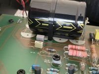
I noticed that on the PCB (below each capacitor) there is a space for 8 smaller capacitors, would it be better to use 8 smaller capacitors (let's say 1500-2000uF each) instead of 1 big capacitor?
As far as I know 8 smaller size capacitors will recharge and "respond" faster than 1 10,000uF capacitor, is it correct?
Thanks
As far as I know 8 smaller size capacitors will recharge and "respond" faster than 1 10,000uF capacitor, is it correct?
Thanks
Attachments
- Home
- Amplifiers
- Solid State
- Adding capacitance to an amplifier power supply