I'm about to build an OPA2132 cmoy from tangent's schematic and I still have 2 BUF634T left, how can add them as buffers?
This is the power supply I plan building powered by 2x 9v:
And what opamp should I use for the power supply? I have some spare LT1028, LT1128, LT1124, LT1057, LT1365 and soic8 OPA827.
Thanks in advance.
This is the power supply I plan building powered by 2x 9v:
And what opamp should I use for the power supply? I have some spare LT1028, LT1128, LT1124, LT1057, LT1365 and soic8 OPA827.
Thanks in advance.
Just as described in that schematic-fit inside the 2132's feedback loop. There's also this exact information in the buf634 data sheet (page 13).
I assume you're going for a gain of one? No need for a opamp in the power supply, especially if that's the circuit you're using.
I assume you're going for a gain of one? No need for a opamp in the power supply, especially if that's the circuit you're using.
Last edited:
I don't know what gain it's set to, I'm following tangent's schematic.
So how do I build the power supply?
So how do I build the power supply?
Well, the cmoy above has a gain of 11, and there is nothing crazy fancy going on here.
I unfortunately think you're at a point where you need a bit of the absolute basics of electronics before you move forward, just enough to at least understand these circuits. Tangent has a pretty good section describing how this circuit works.
I unfortunately think you're at a point where you need a bit of the absolute basics of electronics before you move forward, just enough to at least understand these circuits. Tangent has a pretty good section describing how this circuit works.
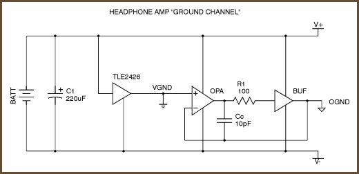
The linked circuit PDF is entirely passive. The "driven" ground is less than ideal. If the two sides are balanced and the drive currents low (which headphones?) then the tle2426 should be pretty okay.
Why not go with the dual battery schematic in the PDF?
Why not go with the dual battery schematic in the PDF?
Nothing is stopping you from your plan. However it won't do much if the bottleneck isn't there. You would probably get better performance by putting the buffer at the output of your virtual ground, which incidentally results in the same topology used in mini3.
The current from the amplifier output needs to go somewhere after travelling through your headphone. In this case it goes into the virtual ground. So your virtual ground needs to be handle the combined current of both channels. TLE2426 handles 10 to 20mA while most opamps can do over 10mA each, so the TLE2426 is the bottleneck for current.
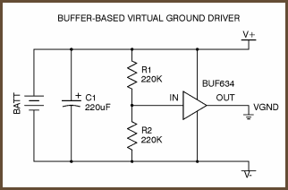
Some designs, instead of using TLE2426 to generate the virtual ground, they use an opamp instead.
The current from the amplifier output needs to go somewhere after travelling through your headphone. In this case it goes into the virtual ground. So your virtual ground needs to be handle the combined current of both channels. TLE2426 handles 10 to 20mA while most opamps can do over 10mA each, so the TLE2426 is the bottleneck for current.
Some designs, instead of using TLE2426 to generate the virtual ground, they use an opamp instead.
Unless your headphones are incredibly low efficiency, then hearing damage will be the limiter long before the rail splitter. The buffers in respective locations are for transients. Likewise, I think a few of these opamps are marginal stability at unity, so be sure to double check data sheets, as that's a pretty trying usage. Might need to hf noise gain the opamp/buffer composite.
Again, which headphones? All of this might be irrelevant if your headphones are sensitive and current demand is low (also why I asked about gain)
Again, which headphones? All of this might be irrelevant if your headphones are sensitive and current demand is low (also why I asked about gain)
If you're using two 9 volt batteries in series you could simply use the connection between the two batteries as ground.
The headphones are HD 439's, 32Ω, 112dB.
I know I could use the connection between the batteries as ground but if one discharges faster it will become unbalanced.
I know I could use the connection between the batteries as ground but if one discharges faster it will become unbalanced.
Well it's silly to add such a virtual ground to a CMOY amplifier. The virtual ground circuit is more complex than the amplifier!
If you're looking at building active virtual ground circuits using nested buffer circuits, you might as well go whole hog and build a buffered three channel amp.
I've been prototyping circuits with the 2426 and the circuit you referenced works very well if the grounds are properly sorted. If they're not, you'll introduce audible distortion; I guarantee it.
And you want the op amp in the circuit. You need the DC precision unless you don't mind DC offset.
The 2426 is only rated at 20 mA. It is intended for line level virtual ground only.
For CMOY, try an op amp based virtual ground sans the buffer chip. The 2426 will work perfectly in this arrangement. You don't need to drive a tack with a jackhammer.
The headphones are HD 439's, 32Ω, 112dB.
I know I could use the connection between the batteries as ground but if one discharges faster it will become unbalanced.
Not as much as you think. The voltages can different (to a point) on each rail without degrading performance. And since your cans are claimed 112 dB/mW, you will never notice the batteries are dying until they're pretty well drained.
The opportunity to use a genuine, reliable, real ground is reason enough. It will work much, much better than any concoction you're scheming. And it's so much simpler.
The ONLY reason I dabble in virtual grounds is because I need some circuits to work off a single 9 volt battery, or a car battery for mobile applications, or else a cheap wall wart. Otherwise I'd never give them a second thought.
You think I should avoid the virtual ground and just use the midpoint between the batteries?
What gain do you recommend?
Is it worth adding those buffers to the amp?
Thank you so much for the help.
What gain do you recommend?
Is it worth adding those buffers to the amp?
Thank you so much for the help.
You think I should avoid the virtual ground and just use the midpoint between the batteries?
Yes. This is the best of everything, and the simplest solution.
What gain do you recommend?
Depends on your intended source. With a typical portable device designed to drive headphones, unity gain will do. A gain of 2-3 gives you a little more versatility with regards to sources and headphones. For old fashioned 600 ohm headphones, I'd go for a gain of 5. You can put some DIP switches on the board to allow for switching gains.
Is it worth adding those buffers to the amp?
Those buffers aren't the best for battery operation. My experience with the BUF634 is that it likes a unity gain circuit, with maximum bias current (I think it's 12.5 mA per channel), and higher voltages (20 volts and up) to sound its best.
You can buy 3 channel headphone amps complete with virtual ground on a single chip. Unfortunately they're all SMD but if you browse Digi-Key you might find a super simple solution that works way better than what you're trying to do. In fact, some of these chips would work great with just one 9 volt battery. I haven't used any of these chips but I intend to check a couple of them out.
Also consider a coupling capacitor for a single ended headphone amp. It works great if the cap is big enough. It provides built in headphone protection too.
- Status
- Not open for further replies.
- Home
- Amplifiers
- Chip Amps
- adding buffer to opa2132 cmoy