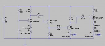
this speaker protect circuit provides a delay turn-on, and fast turn off.
diode D3 represents a PVI which drops about 2.5v.
i want to add an LED to show which state the circuit is in (i.e. PVI-off, LED-on and visa versa)
the trouble is, making a connection to Q2c or Q3c with the appropriate polarity bjt results in the PVI been always on!

diode D3 represents a PVI which drops about 2.5v.
i want to add an LED to show which state the circuit is in (i.e. PVI-off, LED-on and visa versa)
the trouble is, making a connection to Q2c or Q3c with the appropriate polarity bjt results in the PVI been always on!
Can you add an LED in series with the Zener string? The Zener current should be enough to light it up.
What states do you want to indicate? Do you want just one LED that is either on or off depending on whether it's kicked in? Do you want a bipolar bicolour LED that goes from red to green?
Do you have access to transistors and resistors?
Do you have access to transistors and resistors?
When the PVI is off you have supply voltage on Q3 collector. Just use an N channel FET feeding the gate via any high value resistor (say 1 meg for sanity) and add a 15 v Zener for G-S protection. The FET can control the LED directly then. The gate resistor can be any value such as 10 or 100meg even but then leakage of the Zener becomes dominant and would not allow enough gate voltage to develop.
The FET can be any suitably rated device.

The FET can be any suitably rated device.
Attachments
Last edited:
ok, thanks mooly, begs the question what causes the circuit to misbehave with an npn in the same place? base current loading?
Essentially yes, the base will pull whatever current any series resistor into the base dictates. If that current is high enough then the PVI will generate output voltage. I suppose you could use a high voltage Darlington or make one from two separate transistors and keep the 1 meg resistor to the base. I'd bet you could go higher still given the high supply voltage. The Zener would no longer be needed with bjt transistors.

 that looks good and saves a transistor.
i tried out the fet and darlington to drive the led, and they work well.
as for the circuits in post 9 and 11, ltspice indicates voltages of 2.1 and 2.6 across the PVI when it is supposed to be off.
i came up with my own alternative below to avoid fet (i have no small fets) and the darlington (using 2 bjt's)
i put the PVI in the emitter leg to avoid the next bjt's base current and left the dropper resistor in the collector leg
Attachments
Last edited:
Pleased to hear they worked OK 🙂
The circuits from catd should work OK. Remember the PVI volt drop doesn't mean it is 'on', it just means a very small current is flowing such as via the 10k and 1 meg. That would not (I'm 99% sure) be enough to actually give a voltage output on the other side.
The circuits from catd should work OK. Remember the PVI volt drop doesn't mean it is 'on', it just means a very small current is flowing such as via the 10k and 1 meg. That would not (I'm 99% sure) be enough to actually give a voltage output on the other side.
Yes, there is a step in the voltage diagram. But it doesn't matter. If you look at the current, it's only a few microamps. If you use an optocoupler in the LTspice simulation, you can see that the desired voltage/current curve is present at its output.

Attachments
I get around 1 volt output from the PVI (I did a model for these a while ago) with a 300k resistor. If you are using this voltage to control a solid state relay then it should be OK even at that level.


- Home
- Amplifiers
- Solid State
- adding a LED for indication