I'm looking to add a high pass filter at 150Hz with at least 12dB/oct slope at line level.
This is a unity gain, single stage, non inverting second order high pass filter.
Sallen?Key topology - Wikipedia, the free encyclopedia
Download TI's free FilterPro software, pick your topology and frrquencies. It will generate circuit diagram, analysis and even BOM for standard valued components.
FilterPro v3.1 Available Now! - WEBENCH® Design Center Blog - WEBENCH® Design Center - TI E2E Community
FilterPro v3.1 Available Now! - WEBENCH® Design Center Blog - WEBENCH® Design Center - TI E2E Community
.
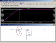
From the way you phrase your question I think you might be sailing uncharted waters? So cool, so shown below is a high pass filter that's kinda-sorta what you want. The filter is no more than the circled components, one capacitor and one resistor. The values as shown are:
C1: 0.047uF
R1: 50k
Line level or not doesn't matter, the same filter works the same way at one volt or a million. The resistor could probably be rated at 1/8 watt, certainly 1/4 watt would do. A capacitor rated at 50 volts would certainly be fine. Of course you don't use formulas to find the component values, you use a calculator: High Pass Filter Calculator
The components to the right of the circled filter are an amplifier stage, they don't enter in.
Wait, you thought it would be that easy? C'mon. The TPA3116D2 board is specified as a subwoofer amp, so it undoubtedly already has a low pass filter on the input (for a low pass filter, reverse the positions of the shown C1 and R1).
Two filters in series (cascaded) are not necessarily a bolt-together operation. Ideally you'd want to know the circuit for the TPA3116D2, and the calculations can get complex. Things could come out sounding...less than great.
But on the other hand, just the shown filter, or something like it, might work fine, and the board won't be damaged because you're still sending in the same audio signal, only minus a few frequencies. So the worst that can happen is you're out the cost of a capacitor and a resistor.
.
Attachments
Last edited:
- Status
- Not open for further replies.