I have a Chinese line output tx that I want to use as step-up input tx, it's 15k:300 so 7:1 but I used as inverted at one DAC output to increase gain & worked well connected to a SET 5687, measured the line OT with scope and included a zobel at the secondary 14K 100nF (to the 15K side) to avoid the secondary ringing.
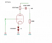
I pulled off the line OT to the DAC to use as step-up input tx for my 26 tube preamp but doesn't have gain, attached the schematic of 26 lineamp and CCS used as load for 26.
The problem is that lower the gain in place of adding gain, I tried without zobel but the sound with a lot of echoes, distorted with less gain than with step-up.
I do some measurements at the line OT:
15K side 1k22
300 ohms side 77 ohms
1220:77= √15,84415584415584 = 3.98 not really 15K:600R = 1:5
Attachments
Last edited:
So you want to know what is downloading your source signal? What is the dc resistance of the 600 ohm impedance winding?
The sources:
DAC output impedance +-50R
Valve Itch possible a couple or 300R
Test are done only with DAC
DAC output impedance +-50R
Valve Itch possible a couple or 300R
Test are done only with DAC
For a low loss connection (9% max) one should maintain the 1:10 impedance relation. So, when the output impedance of your source is X ohm the input impedance of the next stage should be at least 10 times that value. In your case at least 500 ohm.
You could try a buffer in between, like a cathode follower. Gain would be little less than 1 and high fidelity might not be what you want it to be 😉
You could try a buffer in between, like a cathode follower. Gain would be little less than 1 and high fidelity might not be what you want it to be 😉
I tried also adding a grid leak resistor of 110K
Valve Itch phono preamp output impedance 800R
Valve Itch phono preamp output impedance 800R
Last edited:
I do some measurements at the line OT:
15K side 1k22
300 ohms side 77 ohms
1220:77= √15,84415584415584 = 3.98 not really 15K:600R = 1:5
Have you measured resistance? These measurements are probably nonsense as there is no reason to expect the same wire used at both primary and secondary.
It is a lot more useful to measure inductance.
What exactly is your source? An iv resistor?
You should do some basic troubleshooting.
Play a 1kHz sine on the dac and measure the voltage across the 50ohm resistor. Connect transformer 300ohm primary to resistor with the secondary unloaded and take measurements at both primary and secondary windings. Add tube stage.
Play a 1kHz sine on the dac and measure the voltage across the 50ohm resistor. Connect transformer 300ohm primary to resistor with the secondary unloaded and take measurements at both primary and secondary windings. Add tube stage.
Have you measured resistance? These measurements are probably nonsense as there is no reason to expect the same wire used at both primary and secondary.
It is a lot more useful to measure inductance.
What exactly is your source? An iv resistor? NO
You should do some basic troubleshooting.
Play a 1kHz sine on the dac and measure the voltage across the 50ohm resistor. Connect transformer 300ohm primary to resistor with the secondary unloaded and take measurements at both primary and secondary windings. Add tube stage.
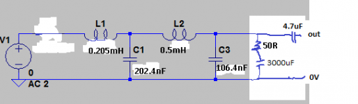
Can't do it see attached schematic of the output filter of the noDac I use.
Attachments
Oooops I forgot I use SET 5687 CCS loaded between the noDac & the 26, surely this is the guilty increasing the output impedance of noDac
Last edited:
Try to check primary/secondary ratio (maybe it's 1:7).
Adding 1Veff (from 5687, for example at 1kHz) to lower side, on the other side the voltage must be 7V.
Repeating this, several times, at different frequencies (from 20Hz up to 50-100kHz) turns out if it is suitable for step up input transformer.
Adding 1Veff (from 5687, for example at 1kHz) to lower side, on the other side the voltage must be 7V.
Repeating this, several times, at different frequencies (from 20Hz up to 50-100kHz) turns out if it is suitable for step up input transformer.
SG 0.250Vrms, 50 ohms source impedance, without zobel.
20Hz 2.61
100Hz 4.8
1K 4.8
5K 2.56
10K 1.28
15K 0.75
20K 0.47
25K 0.3
30K 0.12
35K 0.05
40K 0.04
50K 0.04
55K 0.08
60K 0.036
70K 0.14
80K 0.32
90K 0.16
100K 0.039
20Hz 2.61
100Hz 4.8
1K 4.8
5K 2.56
10K 1.28
15K 0.75
20K 0.47
25K 0.3
30K 0.12
35K 0.05
40K 0.04
50K 0.04
55K 0.08
60K 0.036
70K 0.14
80K 0.32
90K 0.16
100K 0.039
Last edited:
300R side have a center tap that measures the same between the center tap & the 150R of both sides
Freq. Ratio
20Hz 2.52
100Hz 5.72
1K 7.07
5K 1.78
10K 0.74
15K 0.37
20K 0.20
25K 0.063
30K 0.048
35K 0.032
40K 0.028
50K 0.048
55K 0.19
60K 0.12
70K 0.04
80K 0.04
90K 0.04
100K 0.036
Freq. Ratio
20Hz 2.52
100Hz 5.72
1K 7.07
5K 1.78
10K 0.74
15K 0.37
20K 0.20
25K 0.063
30K 0.048
35K 0.032
40K 0.028
50K 0.048
55K 0.19
60K 0.12
70K 0.04
80K 0.04
90K 0.04
100K 0.036
Last edited:
I have a couple of Edcor GXSE5-600-15K pri.15K sec.600R
Freq. Ratio
20Hz 1.15
100Hz 2.59
1K 4.68
5K 3.86
10K 2.96
15K 2.4
20K 2.04
25K 1.79
30K 1.59
35K 1.45
40K 1.35
50K 1.18
55K 1.08
60K 1
70K 0.86
80K 0.72
90K 0.64
100K 0.041
Edcor measures 24R & 258R
Freq. Ratio
20Hz 1.15
100Hz 2.59
1K 4.68
5K 3.86
10K 2.96
15K 2.4
20K 2.04
25K 1.79
30K 1.59
35K 1.45
40K 1.35
50K 1.18
55K 1.08
60K 1
70K 0.86
80K 0.72
90K 0.64
100K 0.041
Edcor measures 24R & 258R
Last edited:
That kind of clears it up.
You have nearly 1:5 @ 1kHz, the low frequencies are depressed because of high output impedance/low transformer inductance and the highs are depressed...dunno why really but a crappy transformer or a capacitive load seem both possible. How is the transformer loaded?
You have nearly 1:5 @ 1kHz, the low frequencies are depressed because of high output impedance/low transformer inductance and the highs are depressed...dunno why really but a crappy transformer or a capacitive load seem both possible. How is the transformer loaded?
- Home
- Amplifiers
- Tubes / Valves
- Add step-up tx to 26 lineamp