Hello forum!
In an effort to have a digital signal feed into my DAC, from my server, I have been using a bare mobo, being controlled with a classic remote desktop app, operated with a Win7 system.
Rrecently I had the idea of eliminating a usb to spdifout dongle that feeds my DAC from the mobo, by accessing the s/pdif out signal, directly from the sound chip an ALC3888s on a small sized mobo, out of an old MSI wind u100 laptop.
My question is, do I have to activate, somehow, the s/pdif out? or I should be able to get a signal as soon as I hook up the wire onto the corresponding pin?
any experience will be appreciated...
b regards
angelo e.
You mean there's an SPDIF header on the mobo? If so, you can directly connect a wire to it and it'll play.
You mean there's an SPDIF header on the mobo? If so, you can directly connect a wire to it and it'll play.
I mean, I have a mobo that utilizes the ALC3888S sound chip, but has no s/pdif output anywhere on the mobo as a header or rca or anything like that, so I thought I might be able to get an s/pdif out tapping directly onto the pin of the chip, it is pin #1 according to its datasheet... and get a ground from around there, and feed that signal to my dac;s s/pdif's input ...
so the question is, if I connect onto the chip's output, will I get a signal, or I would have to activate it somehow with software...
The header might be intended to drive a Toslink transmitter, not a coax input. Apart from that, have a look at the driver settings for the onboard sound.
Ok, this is where I have come to, I taped the corresponding out pin and a ground, but I have not been able to get signal, which makes me think that I might have to activate the s.pdifout, much like it was done on older driver settings. There is no obvious way of doing it and so I am on uncharted waters, trying to make sense out of drivers files like the .inf and imagine what do I have to fiddle with, in order to activate the s/pdif out pin...The header might be intended to drive a Toslink transmitter, not a coax input. Apart from that, have a look at the driver settings for the onboard sound.
any words of wisdom? edit the inf file perhaps?
Check your Windows sound output settings and make sure that the SPDIF output is set as default. BTW, the output actually might not be enabled in the driver, and/or the signal might need to be boosted before it can be used.
Ok, this is where I have come to, I taped the corresponding out pin and a ground, but I have not been able to get signal, which makes me think that I might have to activate the s.pdifout, much like it was done on older driver settings. There is no obvious way of doing it and so I am on uncharted waters, trying to make sense out of drivers files like the .inf and imagine what do I have to fiddle with, in order to activate the s/pdif out pin...
any words of wisdom? edit the inf file perhaps?
Did you check the datasheet to see what is the actual voltage spec of the spdif signal at "pin 1" that you are tapping? SPDIF is a bipolar format. A computer has no negative rail, thus not bipolar in and of itself. Pin 1 could be a lower voltage and/or positive only version of spdif. You may need to add some interface circuitry. If you are versed in electronics this is not so hard, but you need to know what you've got first.
Also is there anything in software (e.g. in the driver) that you need to enable the spdif stream at pin 1?
For interfacing TTL (unipolar 0-5V) signals to spdif (coax) for output, see the very bottom of this web page:
S/PDIF Digital to Analogue Converter
If you want toslink, you will need a toslink transmitter, but you probably know that...
Ok, here is a page off the datasheet, and it is actually pin #48 that I have tapped. Where should I look for GND, if nopt the rail of the chassis?
Also, there is no digital output on the device's driver window, the mobo is out of a wind u100 notepad...
any suggestions? could the spdif be activated by editing the driver? am I making any sense here? it's beyond my knowledge base by far, Thank you all for contributing!!!!
angelo e
Attachments
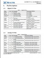
Hmmm, that is sort of useful. It seems that the pin can drive a coax cable directly. The voltage at DVdd is 3.3V and DVss is 0V (ground) according to the datasheet.
Given that info, you just need to AC-couple the output through a capacitor and reduce the voltage while preserving the output impedance. This is very similar to what is shown in figure 6 in the link I posted above - you essentially already have the equivalent of the 74HC04 devices inside the ALC888. If you connect pin 47 to the 100nF cap, and instead of the 360R and 91R shown in figure 6 used 220R and 100R, you should be in business. The junction between the two resistors goes to the coax center wire and the shield should be connected back to the ground near the ALC888 IC, or other convenient ground point that is electrically "close" the the IC.
Given that info, you just need to AC-couple the output through a capacitor and reduce the voltage while preserving the output impedance. This is very similar to what is shown in figure 6 in the link I posted above - you essentially already have the equivalent of the 74HC04 devices inside the ALC888. If you connect pin 47 to the 100nF cap, and instead of the 360R and 91R shown in figure 6 used 220R and 100R, you should be in business. The junction between the two resistors goes to the coax center wire and the shield should be connected back to the ground near the ALC888 IC, or other convenient ground point that is electrically "close" the the IC.
Hmmm, that is sort of useful. It seems that the pin can drive a coax cable directly. The voltage at DVdd is 3.3V and DVss is 0V (ground) according to the datasheet.
Given that info, you just need to AC-couple the output through a capacitor and reduce the voltage while preserving the output impedance. This is very similar to what is shown in figure 6 in the link I posted above - you essentially already have the equivalent of the 74HC04 devices inside the ALC888. If you connect pin 47 to the 100nF cap, and instead of the 360R and 91R shown in figure 6 used 220R and 100R, you should be in business. The junction between the two resistors goes to the coax center wire and the shield should be connected back to the ground near the ALC888 IC, or other convenient ground point that is electrically "close" the the IC.
The problem here though is that his driver does not seems to have support for the SPDIF interface, even though the chip has the hardware support. I know from prior experience that the Realtek chips won't output SPDIF unless it is explicitly set as the output device, and the proper sample rate and bit depth is set.
I would suggest that the OP try using the default Realtek driver from their site (not the mobo manufacturer's driver) and see if they can enable the input before trying any hardware mods... the SMT work is risky and its easy to bridge the connections.
Last edited:
I want to thank you peolple, for the help, actually I have to solve the driver issue or else the chip is like a dead bug doing nothing... currently I am using a usb to coax dongle thing and drive the dac from there... but I wanted to eliminate it... and the wires that go with it...
Have you seen a post or ? that would deal with the issue of playing music from the net or the intranet to a hifi system? an apparatus that would bridge flac and mp3 and what if, with the pre-amp... a diy progect kinda..
Have you seen a post or ? that would deal with the issue of playing music from the net or the intranet to a hifi system? an apparatus that would bridge flac and mp3 and what if, with the pre-amp... a diy progect kinda..
- Status
- Not open for further replies.
- Home
- Source & Line
- Digital Source
- add S/PDIF to a WND U100 mobo