Sure.
Opamps operate in classAB with very low bias in the output stage. When driving a load, this means nasty-shaped current pulses on the supplies. With high supply impedance (as with series Rs) this translates to HF noise on the supplies which is modulated with signal level. Grunge in other words.
I'd try putting inductors in place of your zero ohm bridges and beef up the cap values into the 1000's of uF. Be sure not to share the ground end of these caps with any signal 0V connections.
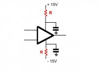
The reason for the resistors is to fail if there is an issue with the op amp instead of overheating and damaging the pcboard. The decoupling capacitors will reduce the supply rail impedance.
I would read the R and the C as simply an RC filter to attenuate some of the variations of the supply lines.
If the opamp output is nearing supplying rails on some transient peaks then a lowering of the supply voltage due to the R will have an impact on performance.
If the output never gets near the supply rail voltage then the opamp PSRR should make the residual line variations inaudible.
The fact that there is some evidence that increasing the voltage at the opamp improves the sound quality tells me that either the output of the opamp is too high or the line voltage is too low.
The solution will depend on which is to be altered.
Also those resistors help to damp any resonances in the supply network (It does not take much series L with a 1000uf or so at the power supply to put a resonance within the opamp gain bandwidth (And actually within the audio band is quite possible).
The problem is made somewhat worse by the very low ESR of modern elcos and ceramic caps, model a 10uF ceramic with a modest amount of series inductance, of a couple of hundred uf of low esr electrolytic with the same to see the issue.
Note that most opamp spice models treat the things as three terminal devices, rather then the five terminal parts they really are.
I use them (Less then 10r most of the time), but usually with several tens of uf of deliberately moderately high ESR elco on the opamp side of things to lower the low frequency impedance near the opamp, I want the class b current pulses on the supply rails flowing in a small tight loop, not going all the way back to the power supply if I can help it.
Big thread over on GroupDIY about this.
Regards, Dan.
i use the 2 red resistors marked on Your schematic, 1 ohm 5 watt ones.
99% of the time i give the opamps regulated power source, with lm7815 regulators.
i found 100 nf local filtering is sufficient, with 2200 uf elco / rail tanks.
between the regulators and the rectifiers i use the cheapo 10,000 uf elcos i came across. ordered a huge lot few years ago, still have like 50 of them around.
I would read the R and the C as simply an RC filter to attenuate some of the variations of the supply lines.
That would be my guess as well.
The fact that there is some evidence that increasing the voltage at the opamp improves the sound quality tells me that either the output of the opamp is too high or the line voltage is too low.
The evidence is anecdotal at best. It may as well be confirmation bias.
~Tom
In mixers with tons of Op Amps it's customary to add a local 10 to 100 ohms resistor per feed pin, basically so that if one IC shorts it's easier to find quickly and if the supply can take it, maybe other channels can keep working.
A small resistor (I've seen 1/8W ones quite often) works as a de facto individual fuse, for peanuts.
Not elegant but practical, imagine fitting 100 small fuses all over the mixer board.
Local decoupling (.047 and .1 ceramics) is , of course, good practice.
That the combination helps lower crosstalk and improves stability, is a nice bonus 🙂
Win-win situation.
i use the 2 red resistors marked on Your schematic, 1 ohm 5 watt ones.
I then tried original 10ohm , reduced to 6.8ohm, to 1.5 ohm, to zero-ohm bridge, and finally a 68uH inductor (all values that I have at my house)
The best from sonically point of view is in effect 1.5 ohm, not the zero-ohm bridge
Also the inductor works quite well but since the cap is 220uF, they form a resonance in the audio band which I don't like to think having it.
- Status
- Not open for further replies.
- Home
- Amplifiers
- Chip Amps
- Add (or delete) resistors in series with opamp's power supply rails