Hi everyone. My father has a very old Grundig CC250 that he loves and he's planning to fix it (belts and other stuff) and, we wanted to add a line in input as he want to connect PC, smart phone and CD Player, 1 at a time.
Luckily I have the service manual of the equipment!:
Grundig CC 250 Free service manual pdf Download
or
CC 250
So, my first idea is to add a simple preamp or buffer or "impedance matcher" (inverting or non inverting?) with a NE5532 (or TL072 or RC4558) in front of the tone control, using maybe the power supply of the Grundig for it. It would be in the red arrow in the next picture:
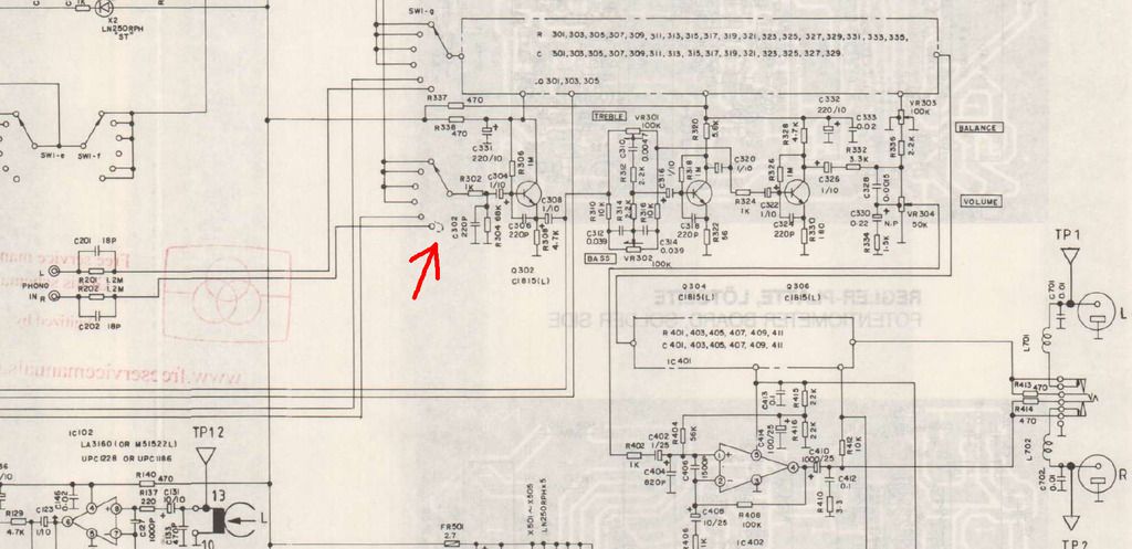
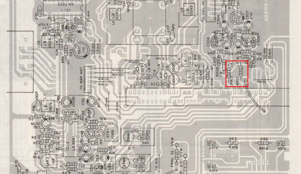
Which is this point (it should read R302 instead of R307) in the board:
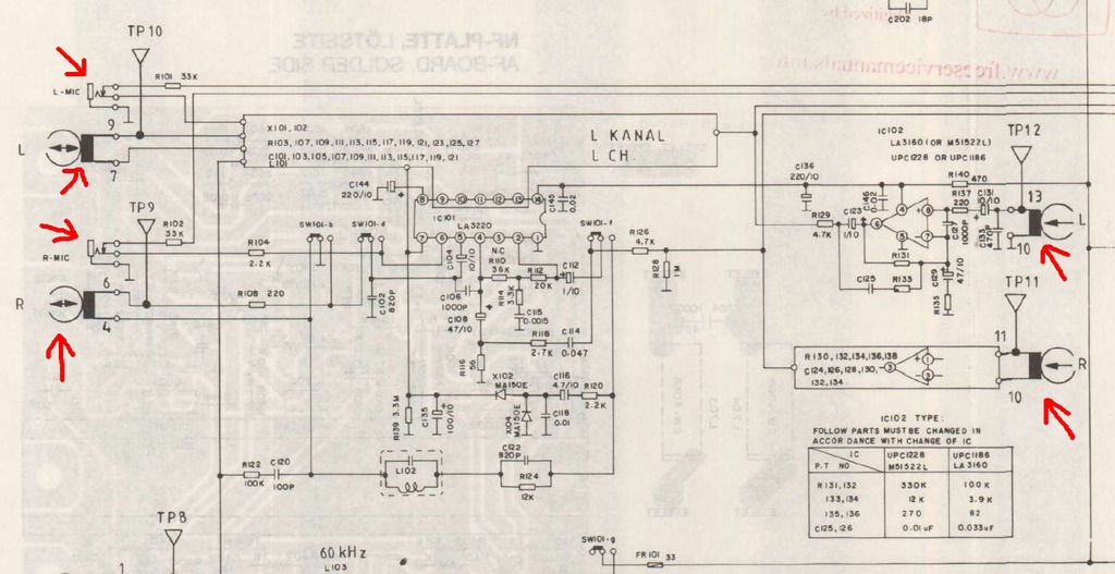
Or what about where the cassette reader heads connect? That should be more difficult right? Or adapt the mic inputs (the preamp has this ALC thing that doesn't sound good for line in, automatic level or gain control, or audio limiter control):
Also where's the RIAA eq? It doesn't seem to be the middle left circuit in the first photo (R201/2-C201/2). Should I even bother to bypass it?.
Now I do not intend to cancel one of the functions of the equipment, I could add a switch to keep the function. If I had to cancel one function would be one of the tapes, the second one. It wouldn't be necessary if adding a switch on front of the tone control...
Now I'n not sure but I noticed that this equipment amplifies all the time, there is no need for example, if you select cassette, to press play for the amp to start running. If true this would make easier to add a line in with my proposed method.
So what do you suggest?
Where do I do the connection and how?
If I have to add a buffer or preamp, what circuit do you suggest? Inverting or non inverting? With gain or not? Variable gain? Variable something else? How exactly do I feed it using the power supply of the Grundig?
Thanks!!!
Luckily I have the service manual of the equipment!:
Grundig CC 250 Free service manual pdf Download
or
CC 250
So, my first idea is to add a simple preamp or buffer or "impedance matcher" (inverting or non inverting?) with a NE5532 (or TL072 or RC4558) in front of the tone control, using maybe the power supply of the Grundig for it. It would be in the red arrow in the next picture:
Which is this point (it should read R302 instead of R307) in the board:
Or what about where the cassette reader heads connect? That should be more difficult right? Or adapt the mic inputs (the preamp has this ALC thing that doesn't sound good for line in, automatic level or gain control, or audio limiter control):
Also where's the RIAA eq? It doesn't seem to be the middle left circuit in the first photo (R201/2-C201/2). Should I even bother to bypass it?.
Now I do not intend to cancel one of the functions of the equipment, I could add a switch to keep the function. If I had to cancel one function would be one of the tapes, the second one. It wouldn't be necessary if adding a switch on front of the tone control...
Now I'n not sure but I noticed that this equipment amplifies all the time, there is no need for example, if you select cassette, to press play for the amp to start running. If true this would make easier to add a line in with my proposed method.
So what do you suggest?
Where do I do the connection and how?
If I have to add a buffer or preamp, what circuit do you suggest? Inverting or non inverting? With gain or not? Variable gain? Variable something else? How exactly do I feed it using the power supply of the Grundig?
Thanks!!!
Last edited:
The phono inputs if you are not using them look like the right spot to modify. It appears to be an input for a ceramic cartridge so all you'd need to do is short across the parallel resistor/cap combination. (Ceramic cartridges do not require external RIAA eq as their internal response is close enough) If levels are too high (unlikely given the proposed sources) you could attenuated the input a bit with a resistive voltage divider. Also consider a 100K resistor across each input jack to avoid pops..
The phono inputs if you are not using them look like the right spot to modify. It appears to be an input for a ceramic cartridge so all you'd need to do is short across the parallel resistor/cap combination. (Ceramic cartridges do not require external RIAA eq as their internal response is close enough) If levels are too high (unlikely given the proposed sources) you could attenuated the input a bit with a resistive voltage divider. Also consider a 100K resistor across each input jack to avoid pops..
Well, the vinyl player is in use (will be after the belt is replaced), but that's the first spot I was talking anyway: the input of the tone control. Do you think it will have unwanted noise or strange eq curve or something? My intention is that it sounds perfect as if it had line in by design.
So you don't see a RIAA there neither?
I don't know if it is ceramic, my father says it could be.
It is clearly ceramic- a 1.2Meg input resistor would trash a mag-needle's signal. A mag-needle input would look a lot like the Tape preamp, just different R-C values.
The clear intent is that signals arrive at the Selector switch already "leveled" and with their right EQ. The tape preamp has the expected EQ. The FM tuner has deemphasis and 19KHz notch. The Phono's 1.2Meg and 18pFd work against the 1meg at the selector switch to give about 6dB boost above 5KHz, a small refinement for a ceramic needle's usual "flat" response. So the Selector switch input expects "flat, needs no more EQ".
BUT looking forward: Q302 Q304 work unity-gain, but Q306 works at gain of 20 or so, THEN comes the Volume control. And Q306 runs on 10V supply, will overload at 3V out, so can not take more than 0.15V input! Indeed the tape preamp is not large gain and the tuner output is attenuated! (R31 R33) Also the power amp works at high gain, so levels through the selector tone boost and Volume chain must be lowish.
Many sources exceed 0.15V. iPod is several tenths of a Volt. Hi-Fi CD deck is often 2V.
Grundig knew *exactly* what sources they gave you. You want to connect "any line out", and the world has changed in 30 years. I think many sources will need to be pot-padded to taste. This could be a back-panel knob only set when a new source is introduced to Grundig. It might like to be on "6" for an iPad and on "3" for a CD/DVD deck.
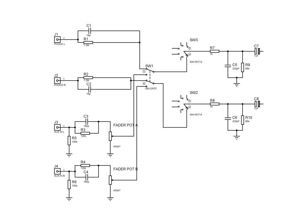
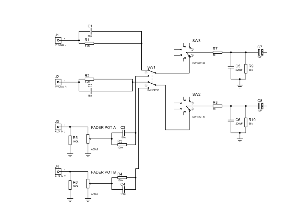
DPDT switch chopped into the Phono feed, and 100K Audio taper pot from the Line In jacks.
The clear intent is that signals arrive at the Selector switch already "leveled" and with their right EQ. The tape preamp has the expected EQ. The FM tuner has deemphasis and 19KHz notch. The Phono's 1.2Meg and 18pFd work against the 1meg at the selector switch to give about 6dB boost above 5KHz, a small refinement for a ceramic needle's usual "flat" response. So the Selector switch input expects "flat, needs no more EQ".
BUT looking forward: Q302 Q304 work unity-gain, but Q306 works at gain of 20 or so, THEN comes the Volume control. And Q306 runs on 10V supply, will overload at 3V out, so can not take more than 0.15V input! Indeed the tape preamp is not large gain and the tuner output is attenuated! (R31 R33) Also the power amp works at high gain, so levels through the selector tone boost and Volume chain must be lowish.
Many sources exceed 0.15V. iPod is several tenths of a Volt. Hi-Fi CD deck is often 2V.
Grundig knew *exactly* what sources they gave you. You want to connect "any line out", and the world has changed in 30 years. I think many sources will need to be pot-padded to taste. This could be a back-panel knob only set when a new source is introduced to Grundig. It might like to be on "6" for an iPad and on "3" for a CD/DVD deck.
DPDT switch chopped into the Phono feed, and 100K Audio taper pot from the Line In jacks.
Attachments
Last edited:
Thank you!!!
You...always...you.. THANK YOU!!!
You clarified me a lot of doubts I had about this thing, seriously, thank you so much for the explanation, because I read that could be that some of this kind of gear uses any kind of eq, and the Grundig have such a deep sound (and lots of power for being only 10watts) that I thought maybe it had a RIAA (or something else) after Q302 (I couldn't recognize it).
But like I asked the other guy, will this have any bad effect in the sound? Could be an even better solution? I'm oriented to "good sound", not simplicity (not that I doubt you solution, but just in case!).
It is clearly ceramic- a 1.2Meg input resistor would trash a mag-needle's signal. A mag-needle input would look a lot like the Tape preamp, just different R-C values.
The clear intent is that signals arrive at the Selector switch already "leveled" and with their right EQ. The tape preamp has the expected EQ. The FM tuner has deemphasis and 19KHz notch. The Phono's 1.2Meg and 18pFd work against the 1meg at the selector switch to give about 6dB boost above 5KHz, a small refinement for a ceramic needle's usual "flat" response. So the Selector switch input expects "flat, needs no more EQ".
BUT looking forward: Q302 Q304 work unity-gain, but Q306 works at gain of 20 or so, THEN comes the Volume control. And Q306 runs on 10V supply, will overload at 3V out, so can not take more than 0.15V input! Indeed the tape preamp is not large gain and the tuner output is attenuated! (R31 R33) Also the power amp works at high gain, so levels through the selector tone boost and Volume chain must be lowish.
Many sources exceed 0.15V. iPod is several tenths of a Volt. Hi-Fi CD deck is often 2V.
Grundig knew *exactly* what sources they gave you. You want to connect "any line out", and the world has changed in 30 years. I think many sources will need to be pot-padded to taste. This could be a back-panel knob only set when a new source is introduced to Grundig. It might like to be on "6" for an iPad and on "3" for a CD/DVD deck.
DPDT switch chopped into the Phono feed, and 100K Audio taper pot from the Line In jacks.
You...always...you.. THANK YOU!!!
You clarified me a lot of doubts I had about this thing, seriously, thank you so much for the explanation, because I read that could be that some of this kind of gear uses any kind of eq, and the Grundig have such a deep sound (and lots of power for being only 10watts) that I thought maybe it had a RIAA (or something else) after Q302 (I couldn't recognize it).
But like I asked the other guy, will this have any bad effect in the sound? Could be an even better solution? I'm oriented to "good sound", not simplicity (not that I doubt you solution, but just in case!).
APOLOGIES!!
I overlooked R304 68K. This has little effect with the low-Z tape and tuner sources, but is key in this form of Phono input.
With 1.2Meg||18pFd to 68K||220pFd plus wire strays, the PHONO input IS "flat" for our purposes. And it will take over 2V of input! Which is reasonable for late ceramic needles.
So you even keep the phono input R-C network. Slash between here and the needle, add DPDT switch, add 2 RCA jacks.
> I thought maybe it had a RIAA (or something else) after Q302
No; then it would act on tape and tuner, which is not what we want. Phono EQ has to be in front of the Selector switch.
And in ceramic pickups the RIAA is "inside the pickup". The big slant the way RIAA is normally drawn is not in the record, it is to correct the rising response of a Magnetic pickup. Which senses velocity. The piezo-ceramic senses displacement. The output is nominally flat. For historic reasons records are cut with a kink 500Hz-2KHz. The vast majority of ceramic needles manage this with resonance and damping inside the pickup. There is a further kink at 50Hz but this is below the range of most gear that uses ceramic pickups. I had thought there was a >5KHz correction, but I was wrong. The Phono input is flat. If you can reach those RCA jacks, you can just yank the wires from the needle and plug in your iPod. As the jacks are probably awkward and not made for regular use, switch and added jacks may be the nice solution.
EQ-- the Volume control has a Loudness network, to maintain bass and highs at lower level. Strict Hi-Fi custom sneers at this. However it is probably a large part of why you and Dad "like" this system. I see no reason to mess with it. But if you "have to", snip the connection to Vol pot tap.
There's no other significant EQ in here (that I have noticed yet!). The tone controls have flat response in center (I have seen rigs where center was deliberately un-flat). The power amp is droopy at 41Hz, and I'm sure the speakers gave up an octave higher, so this just reduces rumble-slap. There's some rolloffs above 20KHz which probably reduces stray AM/Taxi radio reception.
Attachments
APOLOGIES!!
I overlooked R304 68K. This has little effect with the low-Z tape and tuner sources, but is key in this form of Phono input.
With 1.2Meg||18pFd to 68K||220pFd plus wire strays, the PHONO input IS "flat" for our purposes. And it will take over 2V of input! Which is reasonable for late ceramic needles.
So you even keep the phono input R-C network. Slash between here and the needle, add DPDT switch, add 2 RCA jacks.
Ops! Well, thanks to reviewing it! Now it's easier and cheaper!
But with 2v will it be enough? http://i.imgur.com/4PQT5uT.png
For PC could be ok but for smartphones am I going to need more power?
The little ne5532 preamp?
EQ-- the Volume control has a Loudness network, to maintain bass and highs at lower level. Strict Hi-Fi custom sneers at this. However it is probably a large part of why you and Dad "like" this system. I see no reason to mess with it.
You're right, that's why he likes it, it told me the other day "how deep it sounds" whie I was thinking how sort of similar it was to the horrible new mini components: all bass and...nothing else. But this is not so horrible, it still have something nice in it. And the 3 way sealed speakers have an interesting sound too.
For what I just searched that is C328, C330 and R334 or like this http://www.eleccircuit.com/wp-content/uploads/2010/09/audio-loudness-control.jpgBut if you "have to", snip the connection to Vol pot tap.
So it's a center tapped..and I was thinking in replacing the pots...I can forget about that now!!
How can you tell? Is it a complicated equation or with that program to simulate tone stacks? (can't remember the name)The tone controls have flat response in center (I have seen rigs where center was deliberately un-flat).
How can you tell? C410 R410?The power amp is droopy at 41Hz,
(...Now this gave me the idea of adding subwoofers...removing that filter etc...just ideas, will not do...)
When I add the line in I will know, but they don't seem to be that bad...and I'm sure the speakers gave up an octave higher,
R402 C404?There's some rolloffs above 20KHz which probably reduces stray AM/Taxi radio reception.
If you are not adding any components into the path (eg level control) then you could use switched 3.5mm jack socket - eliminates the DPDT switch.
Plugging in your external source automatically switches from phono to external source.
Neat and simple.
I did this to add MP3 capability to a car radio.
Plugging in your external source automatically switches from phono to external source.
Neat and simple.
I did this to add MP3 capability to a car radio.
If you are not adding any components into the path (eg level control) then you could use switched 3.5mm jack socket - eliminates the DPDT switch.
Plugging in your external source automatically switches from phono to external source.
Neat and simple.
I did this to add MP3 capability to a car radio.
Yeah I thought about this! The problem is that the ones I can get are of too bad quality: http://www.allelectronics.com/mas_assets/cache/image/1/9/b/6/6582.Jpg
or flimsy and in need of a pcb, lots of work for the result: https://cdn.sparkfun.com//assets/parts/1/5/8/2/Audio-3.5mm.jpg
The 6.3mm are even worse: http://images.mcmanager.co.uk/images/1413532695620.jpg I can find expensives but they are excesively expensive, like 5 to 1 or more the price ratio.
So if I have to make a preamp for this, well, then it's justified to use the little 3.5mm pcb one. If not DPDT and RCA/cheap 3.5mm is better I think. Thanks for the tip anyway!
Look ok to me.
You could always epoxy the pcb one to front panel & solder cables direct to terminals without a pcb if you like this socket better.
If using a switch, consider having jack on front panel for phone & RCA on rear to permanently connect CD player - 3 position switch - phono, CD & front aux.
You could always epoxy the pcb one to front panel & solder cables direct to terminals without a pcb if you like this socket better.
If using a switch, consider having jack on front panel for phone & RCA on rear to permanently connect CD player - 3 position switch - phono, CD & front aux.
Look ok to me.
You could always epoxy the pcb one to front panel & solder cables direct to terminals without a pcb if you like this socket better.
You'll think it's unlikely and silly but I promise I could easily mess that up! haha... But I'll consider it.
If using a switch, consider having jack on front panel for phone & RCA on rear to permanently connect CD player - 3 position switch - phono, CD & front aux.
Good idea! I'll see if I find one of those.
> with 2v will it be enough? http://i.imgur.com/4PQT5uT.png
Thank You for finding that table!
You really want to build that preamp, don't you?
I would change 1.2Meg+18p to 390K+56p or 120K+180p to find a happy level. (Or go back to the pot idea.) This will be separate from the PHONO input's 1.2Meg+18p.
> How can you tell?
It is a (modified) Baxandall. Q304 is a high-gain inverter. All that other stuff sets the gain. If you center the pots, you can see the impedance A-B is equal to the impedance B-C. The knob-center gain is unity (maybe 0.98 due to non-infinite gain). More poking suggests the extremes of bass gain are 10K:110K and 110K:10K, about +/-20dB. The treble equations are less clear, but clearly symmetric.
Attachments

You really want to build that preamp, don't you?
Haha nope, it's just that IF it's needed I would do it. I'm aiming for sound quality, not simplicity. I've done many circuits before (even not knowing enough of electronics as you can tell, hehe), including a headphone amplifier with a 3 band baxandall tone control, so I'm willing to do one! (well not that one again, the soldering of those many cables was a pain in the rear and the lungs!)
I would change 1.2Meg+18p to 390K+56p or 120K+180p to find a happy level. (Or go back to the pot idea.) This will be separate from the PHONO input's 1.2Meg+18p.
That sounds good. But wait, it's the RC network OR the pot? What about switching to a low value RC network with a pot after or before it.
But I'm not clear on why for this application I still need that resistor-capacitor network. You mentioned that it was needed for phono high-Z, so is a line input or rather aux input (or PC) that "high Z"?
And another question. What's the name of that network? 😱
It is a (modified) Baxandall. Q304 is a high-gain inverter. All that other stuff sets the gain. If you center the pots, you can see the impedance A-B is equal to the impedance B-C. The knob-center gain is unity (maybe 0.98 due to non-infinite gain). More poking suggests the extremes of bass gain are 10K:110K and 110K:10K, about +/-20dB. The treble equations are less clear, but clearly symmetric.
Thanks!
At this point I think you are prepared to just try it.
High level sources (CD deck) can plug right to the existing Phono jacks. Does that work OK?
Weak cell-phones may need less than 1.2Meg in series, so try less. For accuracy in the top octave, increase the C in the same ratio you reduce the R.
If you really need "any" source, the pot with a smaller R suggests itself.
- Status
- Not open for further replies.
- Home
- Source & Line
- Analogue Source
- Add line in to old Grundig CC250