Here is some information on tubelab's version of the source follower drive. My implementation is not significantly different other than what is needed to accommodate the peculiarities of my tube and topology choice for the output stage. He may even have pre-made circuit boards, which would be a real time saver.
Here is some information on tubelab's version of the source follower drive. My implementation is not significantly different other than what is needed to accommodate the peculiarities of my tube and topology choice for the output stage. He may even have pre-made circuit boards, which would be a real time saver.
Cool, that's a lot less complex than I thought. I think I might even understand it. The idea of using a constant current source for the driver triode load makes sense sense and it should be easy enough to set up the CCS parameters to present about the same size load the plate resistor does in the existing circuit. And you can't really go wrong at $1.50 each for the 10M45. 🙂 The 2SK2700 mosfet he uses isn't in stock at digikey or mouser - is IRF820 a substitute?
cool. digikey order already shipped. 🙂 I'll figure out the CCS parameters and give it a try.
Now.. can anyone point me to some discussion on frequency response?
Just playing with the PC, it looks like a gradual increase from nothing below 15Hz or so to a maximum at around 3000Hz and a long, slow decline from there until it's down something like 12+ dB at 15khz. This doesn't seem very flat.
I haven't tried to figure out how much feedback I need to flatten it out, but before I do that I want to get some idea of what the other factors are.... interstage coupling capacitors and their loads? The nature of the tubes involved? other stuff I haven't thought of?
The frequency response you mention is very poor. It should be flat from 20Hz to 20kHz with NFB. Something is attenuating the higher frequencies, possibly excessive fequency correction
(added to prevent HF instability with NFB), possibly the effect of Miller capacitance on a voltage amplification stage, which can happen if a grid leak resistor is too high in value or there is a high series resistance in the grid circuit. Really, without seeing a schematic we're shooting in the dark.
(added to prevent HF instability with NFB), possibly the effect of Miller capacitance on a voltage amplification stage, which can happen if a grid leak resistor is too high in value or there is a high series resistance in the grid circuit. Really, without seeing a schematic we're shooting in the dark.
The frequency response you mention is very poor. It should be flat from 20Hz to 20kHz with NFB. Something is attenuating the higher frequencies, possibly excessive fequency correction
(added to prevent HF instability with NFB), possibly the effect of Miller capacitance on a voltage amplification stage, which can happen if a grid leak resistor is too high in value or there is a high series resistance in the grid circuit. Really, without seeing a schematic we're shooting in the dark.
I posted one earlier in the thread.. the phase inverter and drivers are like this, but using a 6SN7 instead of 12AU7. (i subbed 6sn7 after concluding perhaps incorrectly that the relevant parameters of the two were sufficiently close.. 6sn7 was what i had at hand) -
http://www.angelfire.com/electronic/funwithtubes/images/Amp-Spl-2.gif
(i borrowed this from http://www.angelfire.com/electronic/funwithtubes/Amp-Phase.html)
The output is here:
http://mexico.limpoc.com/~eric/output.pdf
Perhaps the 100k series resistance in the grids of the drivers, or the 1.5M feedback resistor from the driver plates to grids? Or could the output stage be responsible?
eric
Those must be old schematics on Max Robinsin's site. He normally uses 6CG7 these days instead of 12AU7. If you used 6SN7 instead of 12AU7, that's a change for the better IMHO (although SY might argue otherwise - just kidding 😀 ).
A few comments about Max's design:
The 470k grid leak resistor on the first 12AX7 stage is too high for good HF response, because this tube has a high Miller capacitance. 100k would be more like it.
He has no fewer than three coupling capacitors from input to output. That's too many for stability with global NFB, since they would all be within the loop. Even two could pose problems, but you can improve your chances of success by staggering the time constants. The first stage should be directly coupled to the concertina splitter (as in the Williamson), losing the 470k on the splitter's grid and the 10k in its cathode - they're not needed with direct coupling, but you may have to adjust the operating point of the first stage so that the voltages across the second stage are reasonable.
The usual reason for using indirect coupling to a concertina splitter like this is to allow the operating point of the first stage to be adjusted independently, so that the first and second stage currents can be made equal. This enables them to share the same B+ decoupling, since the signal currents will be equal but of opposite phase, thereby cancelling each other. This may seem like a good idea at first glance, but this is definitely not a good idea if NFB is taken back to stage 1 cathode, because it introduces the additional coupling cap which will cause instability. If you're using this design, it may explain some of the problems you've been facing.
If I were you, I'd change to a good implementation of the Williamson design. You can use the same tubes and only a few circuit changes will be necessary.
If I were you, I'd change to a good implementation of the Williamson design. You can use the same tubes and only a few circuit changes will be necessary.
Sounds like a plan. I'm not attached to the current design, I just wanted something that would drive the 815s sufficiently.
So I gather that I want to directly couple the plate of the first 12ax7 section to the grid of the second, and the second half gets equal resistances in the plate and cathode (the "split load") for phase splitting.. then capacitively couple the two phases to the grids of the driver tubes without series resistance. It seems like the driver stage can stay mostly the same? And of course if/when I switch to using CCS loads instead of plate resistors, they can go right in there.
Max's site has a Williamson with two 6SN7's, perhaps I can adapt that to use my existing 12ax7 and 6sn7. Something like this one?
http://www.angelfire.com/electronic/funwithtubes/images/Amp-Williamson-1.gif
The resistor values in the Williamson circuit will not suit a 12AX7. Use the same resistor vaues for the plate load and cathode resistor of stage 1, and the plate and cathode loads for stage 2, as in your original circuit, i.e. 100k, 1.8k, 100k, 100k respectively. Also, use 100k for the grid leak resistor of the first stage. For more gain, you should bypass the cathode resistor of the first stage with 100uF capacitor.
Adjust the resistors of the first stage (including its decoupling resistor from B+, if necessary) to get roughly equal voltages across the second stage's plate load, the tube itself and its cathode load. This is the fiddly part - the joys of direct coupling - but you only have to do it once! As you say, your driver can stay more or less as it is.
As for NFB, I would suggest you connect a 100 ohm resistor beween the bottom end of the first stage's (bypassed) cathode resistor and ground. Connect the NFB to the junction of those two resistors. The overall closed-loop gain of the amp will be very roughly = the ratio of the feedback resistor to the 100 ohm resistor.
Adjust the resistors of the first stage (including its decoupling resistor from B+, if necessary) to get roughly equal voltages across the second stage's plate load, the tube itself and its cathode load. This is the fiddly part - the joys of direct coupling - but you only have to do it once! As you say, your driver can stay more or less as it is.
Ok, this is giving me problems. With the original values (100k, 1.8k) the voltage on the first stage's plate is too high, causing the second stage tube to drop only 25 or so volts.
To get the second stage even (plate load drop = tube drop = cathode load drop)= ~115v) I need the first stage's plate load to be over 400k if I keep the bias resistor the same. That seems too high, doesn't it?
Do I add some of it to the plate load and some to the decoupling resistor? I've seen designs with 220k or so plate loads on a 12AX7, but not as high as 400k...
The 470k grid leak resistor on the first 12AX7 stage is too high for good HF response, because this tube has a high Miller capacitance. 100k would be more like it.
I am puzzled by that. Isn't the HF response dependent on the time constant formed between the (high in this case) Miller capacitance and the source resistance? Whatever is driving this is certain to have an output impedance at least an order of magnitude or two lower than that grid leak, so considering the Thevenin equivalent, there should be negligible difference between 100k and 470k.
qq, to do the direct coupled phase splitter and run the input linearly, you'll have to spend a bit of time with load lines and the 12AX7 characteristics. It's doable. 400k is indeed a pretty high load- I'd be looking at values from 150k to 300k. 0.75-1mA is a good current.
Sorry, I should have given more thought to the resistor values! It should be OK with some adjustment.
Try reducing the cathode bias resistor of the first stage to 820 ohm.
Use a 150k dropping resistor to feed B+ for the first stage from B+ of the second stage, with a decoupling cap of ~10uF.
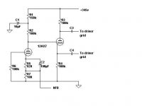
Pleasd see attached schematic.
Try reducing the cathode bias resistor of the first stage to 820 ohm.
Use a 150k dropping resistor to feed B+ for the first stage from B+ of the second stage, with a decoupling cap of ~10uF.
Pleasd see attached schematic.
Attachments
SY, I didn't even think about the OP impedance of the signal source but, as you say, it will probably be just a few k ohms in most cases. I must learn to think outside the box 😀 (100k grid leak won't hurt, though.)
It seems to me the bycicle you are inventing looks more and more like mine in the thread about GU-50 amp. When I've ended with similar process I've discovered that the bycicle was already invented by Altec Lansing. 😀
Nobody's trying to invent anything. Altec-Lansing didn't invent it either, it was already old hat by the time they used it. Like them, we're simply applying an old, straightforward solution to a particular set of circumstances.
ray_moth said:Nobody's trying to invent anything. Altec-Lansing didn't invent it either, it was already old hat by the time they used it. Like them, we're simply applying an old, straightforward solution to a particular set of circumstances.
Let's rephraze: "All roads lead to Rome" (C) 😉
Sorry, I should have given more thought to the resistor values! It should be OK with some adjustment.
Try reducing the cathode bias resistor of the first stage to 820 ohm.
Use a 150k dropping resistor to feed B+ for the first stage from B+ of the second stage, with a decoupling cap of ~10uF.
Ok, that's close to what I arrived at, good to have confirmation. I ended up needing about 650 ohms in the first stage cathode (plus the 100 ohm feedback resistor,) 100k plate load, and 147k for the decoupling resistor to get the concertina balanced. I haven't plotted it out on the load lines for the 12ax7 yet but i bet it's still an ok operating point.
Frequency response is *much* flatter now:
http://mexico.limpoc.com/~eric/williamson-freq.gif
(this is with a 100k feedback resistor from the OPT output back to the top of the 100 ohm resistor in the input stage)
But it still seems to fall way off below 200 hz or so, and to decline gradually as frequency increases. (note that I'm measuring the freq response with a PC whose max sampling rate is 44.1khz, so the top end of that plot is probably bogus data)
harmonic distortion seems roughly comparable to the previous design.
You have hardly any NFB, I would have expected a feedback resistor of around 4.7k to 7.5k. However, if you try this there is a BIG danger of both HF and LF instability. You need to experiment to cure these two problems and there is no "off the shelf" solution because it depends on the parts you're actually using, predominantly the OP transformer.this is with a 100k feedback resistor from the OPT output back to the top of the 100 ohm resistor in the input stage
To avoid LF instability, you need to stagger the time constants of the indirect coupling so that one has about 10 x the time constant of the other. The time constants are about the same in your circuit at the moment, so maybe you should try changing the coupling caps to the grids of the 815 to 0.047uF. This would sound a bit weak without NFB, because it would be lacking in bass, but with enough NFB it should be OK. LF instability usually manifests itself as a low frequency oscillation, known as "motorboating". If it occurs even with the staggered time constants I suggested, then it could be a sign that your decoupling of B+ is inadequate, and bigger caps might cure it.
To avoid HF instability, you will probably need a couple of changes. First, connect a 4.7k resistor in series with a 180pF capacitor across the plate load of the first stage. Secondly, connect a 330pF cap across the feedback resistor, once you've reduced it to 6.8k or so.
You need to experiment to get the right values for HF instability correction. This is very much a trial-and-error thing that only you can do. The usual way is using a 10kHz square wave for input. You want the signal at the speaker (or, better still, an 8 ohm 10w dummy load) to be square also, with no overshoot or ringing. If there is ringing, try increasing the size of the cap across the NFB resistor. If it isn't square but rounded off, it means one or the other of the HF instability prevention caps is too large and needs to be reduced.
To avoid LF instability, you need to stagger the time constants of the indirect coupling so that one has about 10 x the time constant of the other
aha, this clarifies something that was puzzling me - how/why to choose values of coupling caps.
I think I ended up using too little NFB because with the old phase inverter, adding NFB would make the high frequency response go away for reasons you explained earlier.. with this one it doesn't, and indeed it flattens out a great deal with ~6k in there:
http://mexico.limpoc.com/~eric/williamson-6k.gif
I was able to trigger the "motorboating" you described,.. but now that I know what to fiddle with, I'll experiment with staggering the time constants and the rest.
I realize your "scope" is not ideal but see that peak in the response at > 20kHz? That is an indication of HF instability. There is a sign of another at very low frequency. You need to get rid of those and you should be able to, using the methods I mentioned.
These are the unfortunate (but not insoluble) consequences of using beam tetrodes as OP tubes. If you don't use a fairly generous amount of NFB, you will end up with poor damping and, probably, too much distortion. However, if you can get it right, you should have a good-sounding amp with real slam in the bass department.
Williamson would have had to resolve these things, too, if he had used pentodes/beam tetrodes in his OP stage. Since he used triodes (well, triode-strapped beam tetrodes), he didn't need much NFB, therefore he didn't need much gain, so he could get away with 6SN7s everywhere and no phase comensation.
- Status
- Not open for further replies.
- Home
- Amplifiers
- Tubes / Valves
- Add gain before or after the phase splitter?