Hi.
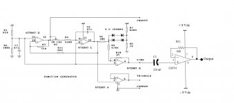
I am building a four op amp function generator. It is the type that comes up when you search for the term "op amp function generator." The frequency range is about 12 Hz to 15 kHz (actual, not nominal). I substituted an NTE997 for the LM348 as that is what I have available. I added the LM741 op amp buffer as I would like to be able to add a DC Offset to the waverform. and I am currently using electrolytic caps and do not want to chance them blowing up. The caps I am using for C3 are
220 uF, 25 V rated.
Another pot has been added for fine tuning. It is a 10 K log pot as has been added between R5, 1 M Log and R4, 560 R. The 10 K log pot is not shown on the schematic.
The problem is that the caps are a few years old and I have nothing else in the desired range that provides a decently sized waveform due to capacitive reactance. So, when the project is left alone for a few minutes the waverform distorts with clipping on one peak or the other. Replacing the caps usually works for a short period of time. Increasing the power supply on one side or the other also works at times.
I believe the problem is due to the age of the caps although I could be wrong.
I have the following questions:
1) Is this altered design good or is it producing my clipping problem?
2) What kind of caps would you use in this situation, price aside?
3) Can you tell me of any caps that are comparable in size and price?
4) Should new a electrolytic new electrolytic cap solve the problem?
The altered schematic is attached.
Attachments
The LM741 does not have a DC path for bias current on its non inverting input. That's likely your problem.
Thanks for the PDF link and the info about the missing DC current return path. It should help a lot. It really puts the need to keep learning in perspective.
And to answer some of your other questions, I would replace the big 220 uF cap with a smaller film cap, maybe 1 uF. Polyester metallized is sufficient. Depending on the size of your resistor from + to ground (I would suggest 100k) this makes your high pass -3dB point at 1.6 Hz. Perfect.
Wow. Almost anything would be better than an LM741. I didn't think that anyone would still even be using any 741 opamps!
On an unrelated note, do you have 10uF||0.1uF from each opamp power pin to ground?
On an unrelated note, do you have 10uF||0.1uF from each opamp power pin to ground?
@zigzagflux: I have yet to implement the DC current return path. When I used smaller value caps such as a 10 uF electrolytic it gave me greatly distorted waveforms. I will have to work it through again with the return path to see what happens.
@gootee: That is not the first time I have received a comment like that. Hah! The Electronic Engineering Technician (EET) course I took used a lot of old but tested teaching materials and so most of the IC's were fairly old types as well.
I asked a question on another forum about using 7476 Dual J-K flip-flops and one of the people who answered said they could not believe we were still using TTL .
Thanks for the tips about the caps on the power pins to ground. I read about them in the PDF referenced above. I will introduce those as well to see what happens. I am learning a lot more than expected by making this fx gen.
I hope that all the changes will be visible on my PoScope - 200 kHz bandwidth capability. I have had it for a few years now and still does a decent job for hobby projects.
Thanks for the help. I will reply when I get some results.
You might not notice any effect from the decoupling/bypass caps on the power pins. But without them, bad things might happen, or good things might not happen as well.
Capacitors should be used wherever something might suddenly try to draw current. The capacitors act as a small point-of-load current source. Without them, the sudden change in current would try to go through the inductance of the supply and ground conductors, which would cause a disturbance or spike in the power supply rail voltage (since V = L di/dt). In future circuits, you can actually calculate the size of caps needed, with a variant of i = C dv/dt: i.e. C = di dt / dv, where di is the worst-case change in current amplitude, dt is the shortest time in which it must occur, and dv is your desired maximum power rail disturbance amplitude. But keep the capacitor connections as short as possible.
Those capacitors perform two basic but essential functions: 1) Decoupling, as in the paragraph above, to "decouple" the transient current demanded, from the power rail's state, minimizing voltage disturbances on the rail, and, 2) Bypassing, which is just the act of creating what is basically a short circuit for high frequencies, so there won't be a "hidden" positive feedback path from the power rails to an amplifier's input, for them. Using bypass capacitance helps to prevent high-frequency instability (ringing and oscillation).
Gootee is on the money with his recommendation of good decoupling.
A long time ago, I used op-amps to build a multi-input pre-amp for someone's particular requirements. It worked fine, except that at switch on, quite randomly, about 1 in 5 times, it would stick in a full rail-to-rail amplitude banshee howl. Naturally, this was feeding into a fairly capable amplifier and pair of speakers.......
A long time ago, I used op-amps to build a multi-input pre-amp for someone's particular requirements. It worked fine, except that at switch on, quite randomly, about 1 in 5 times, it would stick in a full rail-to-rail amplitude banshee howl. Naturally, this was feeding into a fairly capable amplifier and pair of speakers.......
- Status
- Not open for further replies.
- Home
- Design & Build
- Equipment & Tools
- Add DC Offset to Function Generator