I ran out of opa97's. I am just going to replace them. What do you think of some thing like "damp rid" in a loosely sealed container at 150 degrees f?. toaster oven may be. The funk was so bad by one cap it lifted the copper trace off from the board. I just left the lead long, and soldered it at a connection right next to it(on the same trace of coarse). Santa drop off your package yet? The sleigh left over 3 weeks ago😀
I checked all the caps with my LC meter and everything checks out. Still reading 5vdc on outputs. Also checked most of the resistors too.
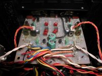
I ordered four A1142 transistors (this is the GFA-555 II) from Mouser and they should be here Monday. These are the ones that look a bit burnt. I did not see a short between emitter/collector on existing transistors.....
The owner is quite insistent on changing the transistors to see if it fixes the amp. I am worried that I will do more damage to the amp...
The Adcom "Expert" claims replacing the transistors should fix it...
There are jumpers on the input board - what do they do?
The A11142 are the two T0-126 transistors on the far left and the two on the far right...
Attachments
Well I did some work on my555 tonight. The output driver transistor is bad on the bad channel. I need to order all new driver to match. Going to go with MJE-15030, and MJE-15031
The thin green electrlytics on each side of the opamp - look to be 4.7uf 50v - I suspect these to be the issue...
I believe they are for the the +v and -v 5v rails to the opamp.
Anyone have a schematic of the GFA-555 II?
I believe they are for the the +v and -v 5v rails to the opamp.
Anyone have a schematic of the GFA-555 II?
Well I replaced both 4.7uF 50v caps and all is good on one channel. The other still shows 4.8v all the time.
I will check for a bad solder joint later.
When I first turn the amp on, it shoots to 12v and drops to 130mv in about 10 seconds on the "fixed" channel. It eventually evens out at around 60mv. I guess this is normal?
I will check for a bad solder joint later.
When I first turn the amp on, it shoots to 12v and drops to 130mv in about 10 seconds on the "fixed" channel. It eventually evens out at around 60mv. I guess this is normal?
Bad news that's not normal.
No 12V shoot and 10 seconds for <100mV offset is allowed for a properly working amp.
No 12V shoot and 10 seconds for <100mV offset is allowed for a properly working amp.
I am having a similar problem to Ben's - may I tag along on this thread?
I have GFA-565 with 27V of offset, which had 3 leaking Elna caps and gunk all over the board.
I removed the electrolytics, the heat sinks, the trimmer, and the op amp from the board, soaked and scrubbed it 3 times on different days with super duper purple-colored Simple Green, and dried it with a hair dryer. I made sure to scrub under and between components as best I could. Afterwards the board looked like new, did not smell, and tested with zero continuity on both sides, as measured at about 16 points, some nearly adjacent, some far apart.
I reassembled with all new electrolytics (well, I couldn't find the new 100uF, 100V ones, so I put back the originals, which were not Elnas and had not leaked, until I find where I put the new ones), installed a DIP socket, and have tried both the original op amp and a new OP97.
I checked and reset bias without a full 80W dummy load workout (had been 46mV, now 23.6mV).
And, yes, the offset is still 27V with either op amp.
So, the question is, what am I doing wrong? Do I need to procure an ultrasonic cleaner?
Should I manufacture a new board from scratch? Should I remove more components?
This is becoming frustrating.
Thanks for your help, and please let me know if I should start a new thread.
- Eric
john65b said:Well I replaced both 4.7uF 50v caps and all is good on one channel. The other still shows 4.8v all the time.
I will check for a bad solder joint later.
When I first turn the amp on, it shoots to 12v and drops to 130mv in about 10 seconds on the "fixed" channel. It eventually evens out at around 60mv. I guess this is normal?
The 12v spike is bad. It settles to close to spec, but the spike is bad news for tweeters for sure. I am have headaches with my 555 also. I found a bad driver on the outputs so I replaced both on that channel. When hooked up to the input boards it goes to 34vdc now

More hunting down bad parts.
Good luck.
Ben
MDchanic said:I am having a similar problem to Ben's - may I tag along on this thread?
I have GFA-565 with 27V of offset, which had 3 leaking Elna caps and gunk all over the board.
I removed the electrolytics, the heat sinks, the trimmer, and the op amp from the board, soaked and scrubbed it 3 times on different days with super duper purple-colored Simple Green, and dried it with a hair dryer. I made sure to scrub under and between components as best I could. Afterwards the board looked like new, did not smell, and tested with zero continuity on both sides, as measured at about 16 points, some nearly adjacent, some far apart.
I reassembled with all new electrolytics (well, I couldn't find the new 100uF, 100V ones, so I put back the originals, which were not Elnas and had not leaked, until I find where I put the new ones), installed a DIP socket, and have tried both the original op amp and a new OP97.
I checked and reset bias without a full 80W dummy load workout (had been 46mV, now 23.6mV).
And, yes, the offset is still 27V with either op amp.
So, the question is, what am I doing wrong? Do I need to procure an ultrasonic cleaner?
Should I manufacture a new board from scratch? Should I remove more components?
This is becoming frustrating.
Thanks for your help, and please let me know if I should start a new thread.
- Eric
Welcome aboard. There is power in numbers🙂
Hopefully this thread will be benificiall to other with similar problems. Ultra sonic cleaners are definitely work the money in this hobby.
Hi Ben, All,
These amps will show some peak of DC offset that will settle down quickly. Almost every single one I've seen will do that (GFA565 types). On some models, the DC servo is run from a single polarity supply. In any case, the DC servo is required to control DC offset and it isn't ready to operate at the first instances after turn on. Don't try and fix a non-fault (part of the design that is normal). I might investigate this more closely if I get a unit that the owner isn't in a rush for. What you can and should do is to ensure that the differential pair is in fact matched. Large DC offsets will reverse bias one transistor and damage it without causing outright failure.
MJ15030 and MJ15031 will be fine but maybe a little slow. I did get the outputs earlier, but sent you an email to confirm. A deep thank you!
Ben, check those low value resistors on the output boards. Also make sure the resistors are all okay on the driver board. They often go open and look just fine to the eye. That DC offset will not harm your tweeters at all unless they are connected without a capacitor to block the DC. It's the woofers that will take the current. You can see them move one way, then settle down again at turn on.
Leakage can develop at higher applied voltages than available from you ohmmeter. Resistors can go high in value if they've been cooked. You also should remove all the parts in the affected area.
I guess the message here is that if you attempt to take a short cut, you will probably not be able to solve this problem.
Eric, did you dilute the Simple Green? You need to do that. 10:1 normally works best and I haven't seen that type you have mentioned. Also, I do believe you need an ultrasonic cleaner, or a ton of scrubbing immersed in cleaner with a toothbrush. No easy outs here. Best to stay in this thread. Get those old caps out and read what I've written above. Lose the socket.
-Chris
Edit: Hey Ben, hi! 😉
These amps will show some peak of DC offset that will settle down quickly. Almost every single one I've seen will do that (GFA565 types). On some models, the DC servo is run from a single polarity supply. In any case, the DC servo is required to control DC offset and it isn't ready to operate at the first instances after turn on. Don't try and fix a non-fault (part of the design that is normal). I might investigate this more closely if I get a unit that the owner isn't in a rush for. What you can and should do is to ensure that the differential pair is in fact matched. Large DC offsets will reverse bias one transistor and damage it without causing outright failure.
MJ15030 and MJ15031 will be fine but maybe a little slow. I did get the outputs earlier, but sent you an email to confirm. A deep thank you!
Ben, check those low value resistors on the output boards. Also make sure the resistors are all okay on the driver board. They often go open and look just fine to the eye. That DC offset will not harm your tweeters at all unless they are connected without a capacitor to block the DC. It's the woofers that will take the current. You can see them move one way, then settle down again at turn on.
John, what kind of cap meter are you using? Some are useful and some don't tell the complete story. Yank those old caps out and install anything as long as the voltage is enough. Even 10 uF is better than a leaky 100 uF. I'd simply replace all those capacitors with new ones if I were you. Your op amp might be damaged or have some electrolyte on it. Did you remove all the parts in that area and clean them? That includes the op amp especially. The new TO-126 transistors may possibly help fix your problem, but they only tend to go if the amp has been badly overheated and had an output stage blow. I have had to replace them before, but not from this cap leakage problem.I checked all the caps with my LC meter and everything checks out. Still reading 5vdc on outputs. Also checked most of the resistors too.
Leakage can develop at higher applied voltages than available from you ohmmeter. Resistors can go high in value if they've been cooked. You also should remove all the parts in the affected area.
I guess the message here is that if you attempt to take a short cut, you will probably not be able to solve this problem.
Eric, did you dilute the Simple Green? You need to do that. 10:1 normally works best and I haven't seen that type you have mentioned. Also, I do believe you need an ultrasonic cleaner, or a ton of scrubbing immersed in cleaner with a toothbrush. No easy outs here. Best to stay in this thread. Get those old caps out and read what I've written above. Lose the socket.
-Chris
Edit: Hey Ben, hi! 😉
I do not have any electrolyte from a blown cap. My input board looks clean albeit a bit dusty.
I will replace the two big 25v 470uf caps next.
These are the only four electrolytic caps on the entire input board.
The last time I was tripped up over a high-ish DC offset it was due to improper grounding of the input. Is this possible? What is the resistance I should see from Input Ground to Chassis Ground?
I get 3Meg ohm from left channel Signal ground to Output Ground on the "working" channel and 146k ohm on the channel with the 5v DC offset.
Should the input grounds be shorted together?
Speaker Output to chassis ground is 0 ohm
Does anyone have a GFA-555 II Schematic?
Hi John,
There's your problem. 100 ohms to speaker ground from the RCA outer shell. The resistors will appear just fine, but they are open.
Get those caps out of there or don't use the amp until they are replaced. The electrolyte is not normally visible to the naked eye.
-Chris
There's your problem. 100 ohms to speaker ground from the RCA outer shell. The resistors will appear just fine, but they are open.
Get those caps out of there or don't use the amp until they are replaced. The electrolyte is not normally visible to the naked eye.
Yes.Speaker Output to chassis ground is 0 ohm
-Chris
OK, now I am getting somewhere. As soon as I short the input signal ground to chassis ground, DC offset goes to 0.
Is this the issue? Do the input grounds need to be grounded to chassis? EDIT - just read your 100 ohm post above
The previous "good channel that went to 12v before dropping to just under 100mv just pops to a couple volts and very quickly returns to zero mv.
What gives? Could this be the magic GFA-555 panacea?
Maybe the best fix is a 100 ohm resistor from sig ground to output ground or chassis ground. It will go path of least resistance - ie go through the 100 ohm resistor before the 147K ohm or the 3 meg ohm, right?
Quick fix?
Regardless, I will replace last electrolytic pair of caps
Quick fix?
Regardless, I will replace last electrolytic pair of caps
Hi John,
Just replace the 100 ohm metal film resistors on the input board. This is to break the ground loop and also to protect the PCB traces in the event of heavier current. It worked.
What you are seeing is normal.
-Chris
Just replace the 100 ohm metal film resistors on the input board. This is to break the ground loop and also to protect the PCB traces in the event of heavier current. It worked.
What you are seeing is normal.
-Chris
Well I took out all the output resistor thinking maybe one is stuck. That was a waste of time. I have the input board out now, and ready for cleaning. I have a bunch of 970's, and 2240's. resistance seems in check on the input side, but I still will test. I am at the point in this hobby where I have figured out to double check every thing before slapping it back together. BTW all the small ga wires coming from the output boards have 80vdc Something is amiss, and it though it was on the output boards.
Ben
Chris I am glad they made it there. I hope their were no issues seeing that it was a gift.
Ben
Something is amiss, and it though it was on the output boards.Ben
Chris I am glad they made it there. I hope their were no issues seeing that it was a gift.
Ben
Hi Ben,
Absolutely no troubles getting the parcel in. Wonderful!
Normally, DC offset without excessive current draw will be in the voltage amplifier stage. There are exceptions and things that can go wrong to change that, but it's a good "rule" to stick to unless there is reason to believe otherwise.
-Chris
Absolutely no troubles getting the parcel in. Wonderful!
Normally, DC offset without excessive current draw will be in the voltage amplifier stage. There are exceptions and things that can go wrong to change that, but it's a good "rule" to stick to unless there is reason to believe otherwise.
No it isn't. You now have some facts to write down. Things you know to be true.Well I took out all the output resistor thinking maybe one is stuck. That was a waste of time.
Any good engine builder will tell you the same thing. Most experienced people will do this. Good habit.I am at the point in this hobby where I have figured out to double check every thing before slapping it back together.
-Chris
Glad to hear they went through OK.
555
OK
I gave the board a bath in a vibrating pool of simple green😀
I tested ever single resistor, and every single diode. All good🙂
Replace all the 970's, and 2240's. I left the differential pair alone. I did not have the parts anyways.
I pulled the caps without looking at them. All the other boards I worked on had a dot to signify neg. This board has a fat bar, and a skinny bar. I am guessing the fat one is negative?
555 done!!!
post 16 I think
http://www.polkaudio.com/forums/showthread.php?t=63766
Thanks guys. I love the feeling of "I did that"😎
24, and 38mv dc😀
post 16 I think
http://www.polkaudio.com/forums/showthread.php?t=63766
Thanks guys. I love the feeling of "I did that"😎
24, and 38mv dc😀
- Status
- Not open for further replies.
- Home
- Amplifiers
- Solid State
- Adcoms with lots of DC offset. Lots!