Hi EchoWars,
OUCH! $215.00 Someone is on drugs at UL!! I did recommend looking at the amps first, since we may be spinning our wheels for nothing. I wish I had written down the spec. It was on a Yamaha service bulleton.
Okay, did a search on the web and I see the thermal fuse ranges between 100°C to 130 °C. Copy [+UL +transformer +"thermal fuse"] into Google search. Hope that helps or leads you to the proper document.
The fuse is buried in the winding and stuck with shellac or whatever they impregnate xformers with these days. Carefully enlarge the existing space to the thermal fuse. Move the fuse with a screw driver while gently pulling on the wires. Soon you will know what it looks like. The replacement, if the same, will slide down in.
-Chris
K-amps said:The little 535 is the only true dual mono power amp adcom made ;-)
It had 2 E+I trafos, rest had single toroids.
Actually, the GFA-2 was Adcom's first dual-mono. 100WPC with dual EI xfmrs.
Regards,
Hi Woodman,
I've worked on lots of GFA-1's. Never saw a GFA-2. What was it like? Does anyone have a schematic for this beasty?
-Chris
I've worked on lots of GFA-1's. Never saw a GFA-2. What was it like? Does anyone have a schematic for this beasty?
-Chris
Hi Chris,
The GFA-2 was a 3x rackmount with the same type of handles used on the 2nd gen GFA-555s. The heatsinks were inside the chassis (like the 535). It used 2 complimentary output devices - the package size/shape was unusual, but they were Toshiba BJT devices.
The GFA-2 was my first "High-End" amp - I bought it shortly after I started working at Adcom (for $100). As I recall, it was very smooth sounding but didn't have the detail and musicality of the 555.
The biggest problem with the GFA-2 was that the xfmrs were mounted on the PCB and would crack the board during shipping. If you ever see one, you'll surely find some PCB trace repairs & extra support under the xfmrs.
Schematic? Geez, I don't think I've ever seen one, even at the factory some 10yrs ago.
I might have some pics I could email you.
Regards,
Hi James,
The pics would be cool. What section do you work in? I did warranty through Pro Acoustics in Montreal, then direct with Adcom. The company name was Micron Electronics in Mississauga.
-Chris
The pics would be cool. What section do you work in? I did warranty through Pro Acoustics in Montreal, then direct with Adcom. The company name was Micron Electronics in Mississauga.
-Chris
Kind of a follow-up...the amp finally showed up, and it does appear that the primaries are open. The transformers don't have a case, so they are easy to examine, but...there appears no way to take them apart further to look for a thermal fuse, and I can't see one anyway.
How about removing the transformers and replacing with a single toroid of appropriate size, like 500VA, 70VCT? There's plenty of room, but I've had bad luck with transformer EMI with the last Avel transformer I got from Parts Express, so I do kinda fear this solution. Otherwise, is there a reason that I shouldn't do this?
How about removing the transformers and replacing with a single toroid of appropriate size, like 500VA, 70VCT? There's plenty of room, but I've had bad luck with transformer EMI with the last Avel transformer I got from Parts Express, so I do kinda fear this solution. Otherwise, is there a reason that I shouldn't do this?
IMHO, 500VA is overkill and will not fit into that chassis. 200-300VA is enough, This will let you drive 2 ohm loads without issues (unless you use constant tones 🙂 ). THe larger GFA-545 had a single 360VA Toroid. I guess the E + I in this are 100-150VA each.
Actually, a 500VA would fit (barely), but if it's that much overkill, I can easily get a 330VA with 35V secondaries, this one here: http://www.partsexpress.com/pe/showdetl.cfm?&DID=7&Partnumber=122-650
Tie the two center secondary leads together and I have a 35-0-35V transformer.
Tie the two center secondary leads together and I have a 35-0-35V transformer.
Echo this is already a 35-0-35... why are we tying centers? Anyway if this fits... though it looks wider than the space i remember, it will work fine. You can actually measure it as you have the amp, I worked on one years ago.
I have used the Avels, they are great for the money, and induce little or no stray fields.
I have used the Avels, they are great for the money, and induce little or no stray fields.
Hi EchoWars,
Have a look near the edge where the wires go in. It may be covered with something - I can't remember. Most commonly you will see three thicker enamelled wires that measure short to the AC leads. One will show the expected primary resistance to on AC lead and open to the other. Temporarily short the open and try the amp on a variac.
Th only times I've seen the primaries open on these are when the amps are run cranked for a long time with a fan on the heatsinks. I have never seen an electrical storm open one. An electrical spike will take out the fuse. Not unless the fuse went and someone stuck a larger size (or foil) in.
Have you checked the price for a new xformer from Adcom, or another EI core? My money is with an EI core for a number of reasons.
-Chris
The Avel uses two secondary windings with no common...it's not a 35-0-35, but a dual 35, so for a common I have to tie the center leads together.K-amps said:Echo this is already a 35-0-35... why are we tying centers? Anyway if this fits... though it looks wider than the space i remember, it will work fine. You can actually measure it as you have the amp, I worked on one years ago.
I have used the Avels, they are great for the money, and induce little or no stray fields.
I'm looking at the transformer, and I can't see a way to do what you say. The enameled wires are buried in there, and the manufacturer of this transformer clearly did not mean for it to ever come apart.anatech said:Hi EchoWars,
Have a look near the edge where the wires go in. It may be covered with something - I can't remember. Most commonly you will see three thicker enamelled wires that measure short to the AC leads. One will show the expected primary resistance to on AC lead and open to the other. Temporarily short the open and try the amp on a variac.
Th only times I've seen the primaries open on these are when the amps are run cranked for a long time with a fan on the heatsinks. I have never seen an electrical storm open one. An electrical spike will take out the fuse. Not unless the fuse went and someone stuck a larger size (or foil) in.
Have you checked the price for a new xformer from Adcom, or another EI core? My money is with an EI core for a number of reasons.
-Chris
Attachments
Hi EchoWars,
You need to snap off the plastic down to where the wires go in. If the primaries are open, you can't do any more damage to these. So go for it.
Another thought. These aren't 100V units are they? I did see some nice mono blocks that failed because they were for a 100V market. Transformers were open, boards overheated and outputs gone. NEC's as I recall.
-Chris
Been gone all day or I would have replied, but you're correct...I can't hurt them more. I'll get to tearing one of 'em up. 
This unit has a switch at the rear to set the line voltage...I saw 120, 240, & 220 as available settings. Certainly if it was set to 100V that would explain a lot.😀
This unit has a switch at the rear to set the line voltage...I saw 120, 240, & 220 as available settings. Certainly if it was set to 100V that would explain a lot.😀
Hi EchoWars,
If I am not mistaken, you have a general export model and that may have been the case. Especially if someone told the owner or previous owner they would have more power in the 100V position. Oh well.
I wish you luck and success with those transformers. I have been able to resurrect some from different makes on occasion. In any event, I would order close replacements if they need to be replaced. EI cores are better at rejecting higher frequency noise than torriods on average.
-Chris
The trafos are not the only thing that could have fried... running the 100v tap on 120v would give you 60v rails and that could have fried the 63v caps on a nice sunny day 😉 . The 535 had nominal rails of 50v. (The 545 had 55v)
There is no 100V setting, only 120, 220, and 240. Perhaps I wasn't clear.
I can't find a EI core transformer to replace this with. Adcom says that the transformers for this are NLA. I can easily find a 330VA 35V+35V toroid to replace the two transformers that are currently in the unit.
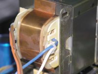
I have busted off the plastic as best I can to get to the enamled wires, but the primary wires for 120V operation enter from the bottom of the transformer, and the mounting flange is in the way of me getting to anything. The flange is spot welded to the rest of the assembly. Like I said, these were NOT meant to come apart in any way.
All I can do if I want to see this running is to replace the transformers with a single toroid, or perhaps some EI core units if I could find some of appropriate size, which so far I cannot.
I can't find a EI core transformer to replace this with. Adcom says that the transformers for this are NLA. I can easily find a 330VA 35V+35V toroid to replace the two transformers that are currently in the unit.
I have busted off the plastic as best I can to get to the enamled wires, but the primary wires for 120V operation enter from the bottom of the transformer, and the mounting flange is in the way of me getting to anything. The flange is spot welded to the rest of the assembly. Like I said, these were NOT meant to come apart in any way.
All I can do if I want to see this running is to replace the transformers with a single toroid, or perhaps some EI core units if I could find some of appropriate size, which so far I cannot.
If cost is not a major issue, go with a Toroid, (or two smaller ones). 🙂 Adcom only went E + I because of cost... The Toroids they used in the 545ii, 555ii were canned and shielded low noise types and rather pricey, you can replace them with an Avel that wont break a bank and work well..
PS: Do you know if the rest of the amp still works?
PS: Do you know if the rest of the amp still works?
Hi K-amps,
Just curious. Why Toroids? You do not want a wide band power transformer. There will be more noise + garbage coming in now plus the extra sensitivity to DC bias on the AC.
I know they are "sexy" and in vogue but I feel they are a poor choice overall. Plus you have to pay more to attain these drawbacks. That and the case is high enough for an EI core. It's not like it's a 2 U amp chassis.
-Chris
Hi EchoWars,
It's still a general export model. Too bad you can't get to the windings. The fuse would be at the common end tap, not the 120V tap. I was just hoping you could get to them.
Now might be a good time to feed some AC from another transformer via a variac. It can be a slightly lower voltage and current since you aren't doing a power test. This will tell you about the actual state of these amps before you get too far into them.
-Chris
- Status
- Not open for further replies.
- Home
- Amplifiers
- Solid State
- Adcom GFA535..Bad Transformer?