Have a customer's 7500 on the bench now. Traced the blown fuse to modules one and five and have disconnected them to test the other three, which are working fine.
The problem is that after removing the screws that hold the PCB and heat sink and the RCA jack, the module is still captured by the two 5/16 nuts that connect it to the binding post, which is in a cramped space.
Normal socket is too short to get past the shaft. Deep socket is too long to fit in there when on a ratchet.
I managed to loosen the top nut with a 12" longnose pliers, but can't get my hand into that space to loosen and later assemble that connection.
Am wondering if anyone has a better solution or suggestion for a special tool that can do the job?
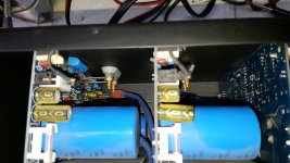
Attachments
It's hard to tell the actual space you have to work with but I use small combination ignition wrenches from Craftsman/Sears in situations like this. I'm completely rebuilding a SAE 2600 at the moment and used this type of wrench to loosen the binding post nuts.
Is it possible to remove the filter capacitors with the boards in place?
Craig
Is it possible to remove the filter capacitors with the boards in place?
Craig
Has to be a ratchet. There's about 12° of swing room for the handle. So an open end probably won't work, even a 12-pointer. And won't work for the bottom nut because the handle is blocked by the upper nut/shaft.
It is probably possible to remove the upper capacitor, but not the lower one, which also impedes access. Those combination ignition wrenches need a lot of rotational swing room to do their jobs.
What might work is an intermediate depth socket--deeper than a standard socket, but not as long as the deep sockets I have. I just need 2/3" more depth to accommodate the shaft of the binding post.
If I manage to get the nuts off, I'm also wondering how I'm going to get them threaded back onto those when the time comes. There is some value in the extension of the shaft, so I could get the nut placed with a long nose pliers, then try to turn it with two screwdrivers to substitute for my fat fingers which can't get into that tiny space.
I wonder what special tool Adcom used when they built these?
That was my first thought. It is, but only by removing the screws to every module and the power supply components. Essentially, a total stripdown. Then we have five modules, dangling from their speaker connections, placing a lot of stress on the solder joints at the PCBs. The chassis would have to be on it's side to work from the bottom, causing all of the modules to sag to one side. Risky.
All you should need is a 72 tooth 1/4" ratchet that will give you the ability to turn a nut or bolt with minimum 5 degrees. Or you could get a twist handle ratchet once on the nut or bolt you can rotate the handle and it turns the ratchets making it great for tight spaces.
Blackhawk 1/4" Drive Rotator Ratchet By Proto GW-9946R | eBay
Blackhawk 1/4" Drive Rotator Ratchet By Proto GW-9946R | eBay
Calling ampexperts, I have this same problem!
I have a GFA 7500 with a bad module. How did you get those binding post off?
I feel like this XKCD is appropriate:

I have a GFA 7500 with a bad module. How did you get those binding post off?
I feel like this XKCD is appropriate:
Take the top cover off and put a couple of screws in the angle piece that holds the transformer to the front face. also add one to the corners were the front face meets the side panels. Now put the amplifier on its back panel with front face up. Position 2 x 4's on each end to hold it up and not damage the binding posts. now take the bottom cover off which will involve removing the stby power supply module from the bottom panel. remember to add a couple of screw to the transformer angle piece to the front face so it holds it up. now you can come in with a shorty wrench and take the amplifier module that is closes to the right side looking from the top and front off amplifier. once you get that out the others are easier to get to. It's like peeling back an onion. I have two of these that I had to restore, and its tight. Wish I had a easier way to show you, but this worked the best for me. Good luck. Its sucks either way....
rcfarmer, thanks for this!
I am trying to decide if I am up to this challenge or not.
This module works, but it takes longer than the other channels to turn on. I also noticed that if I pull the amplifier power cord out of the wall it is one of the first to turn off. I assume some kind of bad cap or something.
I am trying to decide if I am up to this challenge or not.
This module works, but it takes longer than the other channels to turn on. I also noticed that if I pull the amplifier power cord out of the wall it is one of the first to turn off. I assume some kind of bad cap or something.
Last edited by a moderator:
Yea that sounds like caps that are climbing in capacitance around the 555 timer and it changes the time constant and making the amplifier delay turn on. Be very careful when recapping these modules. Very easy to pull the via's or there version of an eyelets out of the PCB when recapping. These are elite capacitors and there okay, but they have a hard time going longer than 20 years without issues. I have a 118lb adcom 7807 that I have cap problems on every module around the 555 timer that was causing all the amps to be stuck in thermal protect. 1 channel that had blown outputs. The amplifier was from 2004 not even 20 years yet. The other issue might be trying to find the filter caps as it's getting harder to find qty in the local suppliers. Just take your time. Also you can take the side off and use the bottom cover with transformer and face plate attached as a test platform. If you have anymore questions let me know.
- Home
- Amplifiers
- Solid State
- Adcom GFA-7500 Amp Module Removal