All,
I'm new to the forum, but impressed with all thats on here! Hopefully, someone can help me understand my issue.
I was given an Adcom GFA-7000 with two bad channels (amp has 5 identical mono channels).
After purchasing the schematics from Adcom, I was able to debug and figure out the issue.
Both bad boards had a resistor that was blown open. The odd thing to me is that it was the same resistor on both boards (R27). Given the odd nature of the fact that the same resistor was blown on both boards, I checked out it and the matching resistor (R35) on all the channels. I found that the resistor values of all of these resistors were creeping up. I measured 55K, 59K, 63K, 70K, and some at 50K. The nominal value is 49.9K.
So, replacing the resistors with 2x 100K resistors in parallel (I didn't have access to 49.9K, but I hand matched the values) got the bad boards to work. Also I proactively replaced all the other resistors on all channels since they all appeared to be showing signs of degredation.
My question is this - what do these resistors do, and why would these resistors be showing failures? Is there something in the circuit causing them to over-current? They're not in a thermally hot part of the amplifier, so I don't really expect thermal degredation to be the cause.
I only ask because I want to make sure that the amp isn't going to fail again in short order. If changing the resistors from 1/8th watt to 1/2 watt would fix the problem, I'd rather do that now (since I'd like to sell the amp).
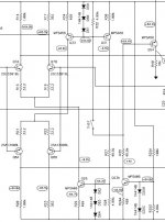
Attached is a portion of the schematic. I don't want to repost the whole thing due to copywright fears.
Any help in shedding light on this situation would be greatly appreciated! Also, if anyone wants to purchase said fantastic sounding beast, let me know.
Thanks!
I'm new to the forum, but impressed with all thats on here! Hopefully, someone can help me understand my issue.
I was given an Adcom GFA-7000 with two bad channels (amp has 5 identical mono channels).
After purchasing the schematics from Adcom, I was able to debug and figure out the issue.
Both bad boards had a resistor that was blown open. The odd thing to me is that it was the same resistor on both boards (R27). Given the odd nature of the fact that the same resistor was blown on both boards, I checked out it and the matching resistor (R35) on all the channels. I found that the resistor values of all of these resistors were creeping up. I measured 55K, 59K, 63K, 70K, and some at 50K. The nominal value is 49.9K.
So, replacing the resistors with 2x 100K resistors in parallel (I didn't have access to 49.9K, but I hand matched the values) got the bad boards to work. Also I proactively replaced all the other resistors on all channels since they all appeared to be showing signs of degredation.
My question is this - what do these resistors do, and why would these resistors be showing failures? Is there something in the circuit causing them to over-current? They're not in a thermally hot part of the amplifier, so I don't really expect thermal degredation to be the cause.
I only ask because I want to make sure that the amp isn't going to fail again in short order. If changing the resistors from 1/8th watt to 1/2 watt would fix the problem, I'd rather do that now (since I'd like to sell the amp).
Attached is a portion of the schematic. I don't want to repost the whole thing due to copywright fears.
Any help in shedding light on this situation would be greatly appreciated! Also, if anyone wants to purchase said fantastic sounding beast, let me know.
Thanks!
Attachments
rings a bell ...reminds of a circuit discussed almost 5 years ago that will only work with 40.0 volts ....bit more and your mosfets are blown to the moon .... what ever ... this is in the past now
it also rings a bell and remind me how most of elektor circuits work ....need 49.928 ohm resistors and BC546 with hfe of 139 .... if resistor is 49.528 or BC 546 has hfe of 149 then the amp missfunction or present offset .... he he he ...done it again !!!
ok ... beyond jokes ( that are true based ) ... obviously if in the collector of Q 31 there is more than -6.5 volt ( indication that other voltages might have drifted for any reason ) one ore more resitor could be under more stress ... so its either your amp has been seriously stressed in the past and now resistors with wrong values make the all amp unbalance in various stages ...or simply the quality of resistors is low regarding thermals ....so simply replace them ...
since you have a schematic verify all check points to see what is going on and then decide what to do ...
regards sakis
To answer your questions:
R27 provides bias to the voltage reference for the constant current source feeding the PNP diff pair.
It has 60V across it all the time, and thus has to dissipate about 72mW.
A 1/8th watt part is inadequate for this level of dissipation, I would use a 1/4W part spaced above the board, or a 1/2W part on the board.
R25A should also be examined, it is dissipating about 170mW, so I would want a 1/2W part spaced above the board.
also, realize that some 1% tolerance parts may be more sensitive to stress than 5% parts if their manufacturing process is different. 5% parts are made in bulk with standard processes, but some processes for 1% tolerance resistors include laser trimming of the carbon or metal film, which means burning off some of the material on the substrate to increase the resistance. this results in a narrower conductive area on the resistor substrate. the current density through the remaining resistor material is locally increased adjacent to the "cut". this makes the adjacent area more susceptible to thermal and electrical stresses. this is a problem mostly with metal or carbon film types that have been laser trimmed. the more common method of pre-sorting doesn't have the same drawbacks, since the material on the resistor isn't altered. the sorting process takes the run off of the production line and tests all of the resistors. those that are within 1% of the target value are diverted to be 1% parts, and the rest go into the 5% bin.
personally i try to avoid circuits that require 1% or better parts. there are certain places where they may be needed and that's ok, but i would rather have a good design that doesn't require tight tolerances to work well.
personally i try to avoid circuits that require 1% or better parts. there are certain places where they may be needed and that's ok, but i would rather have a good design that doesn't require tight tolerances to work well.
Guys,
Thanks for the advice. I'm not sure why 72mW dissapation constitutes needing a 250mW or 500mW resistor (as versus a 125mW resistor), but I'm game.
R25A looked good on the boards, so I'm really just thinking that the 49.9K resistors that were put on these boards were just a bad batch.
Has anyone seen these resistors go bad before in a design similar to this? I just thought it was odd that resistors would pop instead of the power transistors or power caps.
Thanks again!
The 125mW rating is at a specified temperature and is 'absolute maximum' for long term use.
Parts should be de-rated for ambient temperature, how they are mounted on the board, etc.
A 250mW part is probably adequate, but I would space it above the board.
Was the board discolored at all?
Parts should be de-rated for ambient temperature, how they are mounted on the board, etc.
A 250mW part is probably adequate, but I would space it above the board.
Was the board discolored at all?
I'm glad I found this post! I just bought a GFA 7000 on eBay with two channels out. I hope you guys just saved me a lot of time. I'll know in a couple of days. Kudos to everyone on this thread!
Last edited:
I got lucky, my amp had blown fuses that didn't blow when I powered it back up. Seems to work fine. The only issue is the two channels that had blown fuses have some buzz going on. It's only those two channels. I'm going to check interconnects etc. before I blame the amp. Anyone have a suggestion if the patch cords aren't the problem?
I just got the amp and all of the amp modules seem to have never been disturbed. It does however, appear that this amplifier has been wet. But only the left and right channels were out. I'm truly surprised that the fuses didn't blow was soon as I hit the power. The left channel as .1 volt more output than other channels, but signal on the scope was clean for all five. I will have to think about replacing the caps if I can't get rid of the buzz. Thanks.🙂Old electrolytic caps?
Should have posted earlier...Checked cables and turned the system back on the next day, no buzz. It's still silent. Must have just had a cable not quite on far enough. Amp is still great.
THANK YOU SO MUCH!!!!
My GFA7000 is now fixed, thanks to your effort on this post.
Yes the R27 was indeed the culprit. I didn't have 49.9 resistor, so I used three... 47K + 1K + 2.2K... made it a 50K and it fixed the buzz problem.
YEEEEEEHAAAAAWWWW
My GFA7000 is now fixed, thanks to your effort on this post.
Yes the R27 was indeed the culprit. I didn't have 49.9 resistor, so I used three... 47K + 1K + 2.2K... made it a 50K and it fixed the buzz problem.
YEEEEEEHAAAAAWWWW
- Status
- Not open for further replies.
- Home
- Amplifiers
- Solid State
- Adcom GFA-7000 Amp Issue (Need Advice)