Hi Ben,
There we go! You looked. 😀
MPS-A13, you can use MPS-A14. Since they are darlingtons, they are difficult to match with transistor testers. You can not mix types.
-Chris
There we go! You looked. 😀
MPS-A13, you can use MPS-A14. Since they are darlingtons, they are difficult to match with transistor testers. You can not mix types.
-Chris
mjraudio said:JamesW, Thanks! I'm tracking them on DHL and I will get them next Thursday.
Will post pics and my initial report then. I hope that it can work.
If I am able to fix the broken amp I think I will also want to replace the electrolytic capacitors on the input board of the other amp to prevent future problems.
What brand/type do you recommend?
I usually use Nichicon 105 degree electrolytics - if cost is no issue the Black Gates are mighty nice.
ben62670 said:nothing hooked up to the amp power on -12 volts both channels
- 12v for your servo output? That would indicate that your servo is at maximum output swing - double check the voltage reference diodes (Adcom J2) they should be the exact voltage for + and - . I think they are 6.9V reference zeners in series for a total of 13.8V at pin 4 & 7 of your opamps. Do not reference chassis ground as it is floating.
Cheers,
Hi Guys,
I too have a pair of these I've been working on. Typical deal, the electrolytics leaked all over the input boards.
Fusible resistors were gone. Replaced.
Servo controller was toast. Replaced.
All small signal transistors checked. Replaced those that were blown.
Still couldn't get the offset down.
Figured out that the leakage from the caps wicked it's way up into several resistors. They physically look PERFECT - but if you remove them from the boards and start measuring you will find that they are not.
They are not open but don't measure with correct values either. I gently pulled on one lead of a suspect one and the lead pulled right out! It was corroded inside under the ceramic coating!
I was tipped to this on a website I found by someone who repairs these things. I don't remember the site, but as a rule they change all of the resistors on the boards. I thought this was a bit overkill until I found the corrosion in one of mine.
They also recommend replacing the driver transistors at the same time even if they're still good. Don't know if I agree with this, but I suppose it couldn't hurt and they're not expensive.
I've never run into anything like this and I've been repairing gear for a long time.
I'm just ordering all new Dale resistors for each board. In the time it takes to test them, might as well just replace them all.
I've spent WAY too many hours on these things as it is. 😱
Just a tidbit from what I've run across in mine.
Good luck,
Hi Steve,
The electrolyte needs a very thorough cleaning.
Take the board out of the amp and remove the capacitors and bias pots. If you can get an ultrasonic cleaner, use a dilution of "Simple Green" and water, about 10:1. You can go up to maybe 5:1. Clean the board in there for two sets of 6 minutes resting 10 min in between. Once done, rinse well under clean water, then blow the water out from under any parts. Heated drying helps after this.
I've repaired a few and they come up great. The trials to clean these before were brutal. I lost a lot of time cleaning. The boards looked great but they were still leaky.
Repopulate with new caps and reinstall the bias controls. Check other component leads for corrosion and replace if needed. That should do it although you may need to repair some foil.
-Chris
Thanks Chris!
I'll give it a try. I have an ultrasonic cleaner so it should be easy.
I appreciate the tip!
I'll give it a try. I have an ultrasonic cleaner so it should be easy.
I appreciate the tip!
Hi Steve,
Good luck. Let us know how you do on it.
As James indicated, also check those J2's. They are precision regulators and really should be very close to 6.9 VDC each. I have seen them damaged. Zeners need not apply in this location.
-Chris
Good luck. Let us know how you do on it.
As James indicated, also check those J2's. They are precision regulators and really should be very close to 6.9 VDC each. I have seen them damaged. Zeners need not apply in this location.
-Chris
anatech said:Hi Ben,
Install shorting RCA plaugs into the amp inputs, disconnect all speakers.
Turn it back on and measure the DC offsets. Anything over 50 mV is broken. DO NOT CONNECT THE SPEAKERS IN THIS STATE!!!!!!!!
-Chris
@anatech: Can I follow this process of shorting out the RCA input (RCA positive shorted to RCA negative input) on the GFA-565 and test for offset?
When I remove the input boards on my 565 to clean them, I will remove the bias controls and the electrolytic capacitors, should I also remove all the film capacitors and large resistors as well?
Also,
How do you test a transistor (3-4 leads) to see if it is good? The two transistors on the 565 input stage need to be matched, is it difficult to match them?
I would like to replace all the resistors on the input board. But the list in the service manual of metal-film 1% resistors for the input boards is quite extensive and they are all labelled as the same manufacturer part RN14K2E, but each have varying values for example one is 1/4W/10ohms while another is 1/4W/33.2ohms. If I cannot find the original parts, what would be a good alternative to those resistors?
Hi mjraudio,
-Chris
Yes, that is the factory approved method for checking DC offset.Can I follow this process of shorting out the RCA input (RCA positive shorted to RCA negative input) on the GFA-565 and test for offset?
Remove only the trim controls and electrolytic caps. The rest of the parts will not be damaged. You could also remove the op amps so you can get a better clean. Also check the voltage references for corrosion. You will replace all the electrolytic caps anyway, re-install the trim pots in their original locations (mark them when they are taken out).When I remove the input boards on my 565 to clean them, I will remove the bias controls and the electrolytic capacitors, should I also remove all the film capacitors and large resistors as well?
Use a transistor tester. Darlingtons often don't test properly. You may need to make your own jig for this. I see some reading in your future. 😉How do you test a transistor (3-4 leads) to see if it is good? The two transistors on the 565 input stage need to be matched, is it difficult to match them?
Don't do this! Unless one is blown or damaged, do not touch them. They will be fine.I would like to replace all the resistors on the input board.
-Chris
I'm working on a GFA-585, and looks like problems with the voltage reference 'diodes' (schematic refers to them as 'Adcom J2', and gives them a zener symbol). Just thought I'd note here that the drop-in replacement appears to be the National Semiconductor LM329.
FWIW...
FWIW...
Hi,
Remember that if you are having problems, the parts must be cleaned off carefully or replaced. The op amp is a low current draw type, so if you install a standard op amp, you will probably lose regulation. So, unless your supply for the op amp is 7 V or 0 V, the regulators are probably fine.
-Chris
They will work just fine.Just thought I'd note here that the drop-in replacement appears to be the National Semiconductor LM329.
Remember that if you are having problems, the parts must be cleaned off carefully or replaced. The op amp is a low current draw type, so if you install a standard op amp, you will probably lose regulation. So, unless your supply for the op amp is 7 V or 0 V, the regulators are probably fine.
-Chris
I fully admit that this amp makes me feel pretty inadequate as far as troubleshooting. 
Opamps and the small caps on the driver boards have already been replaced (opamp is now a OP97). The small caps are Panasonic FM & FC.
One channel had a blown 10A fuse on one of the supply rails, which was replaced and that channel seems to work. Other channel has offset that is all over the map...starts out on power-up at something like 4V, and the servo slowly corrects it...if you wait long enough.
The other channel (that had the blown fuse), has offset of about 15mV or so. Servo can't seem to do better than that for some reason. And there's no sign of what might have caused the blown fuse.
I don't think I like this amp.
Hi Glenn,
The op amps are fine for that amp. The capacitors used should be fine of course.
Now for the fun stuff. You can always tell how a servo is working by checking the voltage on the output. If it's railed the proper way to correct an offset, the problem is not the DC servo. If, on the other hand, the output is not the correct polarity to fix the offset - you do have a problem in the DC servo somewhere. You could always pull the op amp out to see where the output will sit - uncorrected (by servo action). Some Adcom amps will have a substantial DC offset with no servo action because they were designed to use the servo correction. A good look at the schematic to see what the diff pair looks like will tell you the answer to that question.
You can always check the voltages on the input pins of the servo and then check to see if the output voltage makes any sense as well.
It does appear that this amplifier has been repaired before, so the next (and obvious question) becomes "was the repair done properly?". I have had to redo repair work often enough so that the first place I check is where the earlier work was done. Saves a lot of my time. The fact that you have DC offset wandering around seems to point to an incomplete cleaning job. Perhaps they forgot to clean the parts?
I would start from scratch and assume nothing was done. Make sure you clean everything. I'm going to bet you have assumed that a proper job was done, when in fact something has been missed.
Now, have a look at how far I've had to go on this one so far. All I have done so far is to remove the components in the areas where there was fluid confirmed, then quickly wiped the PCB surface. Next on the hit parade will be flux on the traces and pads, followed by solder wick to remove all excess solder. After that, flux remover with tooth brush and inspection. Only after I do these things will I begin to really clean the PCB. Testing the components for damage follows a wash cycle for these parts. Only after I am sure that all this evil stuff is gone will I begin to reassemble these boards. I will also take this opportunity to match the differential pair and any other pairs that might benefit from matching.
I practice what I preach, no matter how much it hurts some times.
Good luck on this one, Chris
Attachments
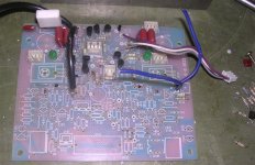
Wow! That's not encouraging...
Looks like you finally talked me into buying that ultrasonic cleaner. Dang! I suppose it'll be nice for the knobs 'n such.
Yes, apparently it has been repaired before, although it is hard to tell. The soldering is first-rate, and if there are parts swapped besides the opamps and caps, then they appear to be Adcom originals. Perhaps there was leakage, and the board was not thoroughly cleaned...?
You mention "remove the components in the areas where there was fluid confirmed". I don't see or smell anything on the boards. I do plan on taking the boards out for the ultrasonic cleaning, but if I'm gonna start stripping parts wholesale I wanna know why, and how to determine if I need to strip the whole board, 'cause that don't look like fun...
Hi Glenn,
If you heat up the solder on a component, you can hear a hiss sometimes, but the odor is the real clue. Then, remove parts a little past that to be sure. This one is bad, but it looked all original. If the bottoms of the capacitors are pretty wet, you can be sure the fluid has gone traveling. The caps on this one were soaked with drips on them. 🙁
You're right, a lot of work. But, the best thing to do is not to over think it, just do what you know needs to be done. If you think on it too much, you will either not clean back far enough, or you'll never start. Just nut up and do the work.
The ultrasonic cleaner is great for knobs, screws and any mechanical parts that need cleaning. As I've said before, your wife will love it, it cleans jewelry extremely well.
-Chris
Echowars,
Forgive me if you've already done this, but did you check the resistence of your negative terminals to chassis ground? Should be 110 Ohms from the RCA to the AC gnd, and 10 ohms from neg binding post to AC gnd.
I'm going up to Boston next week to pick up a 585 for repair. If you need any support, I'll have an open unit on the bench soon.
Good luck,
Hi James,
Now there is a solid, basic problem!
See how we expect another person to cover the basics so that we don't even mention them?
I am reasonably sure Glenn has tested that, but one never really knows for sure!
-Chris
Now there is a solid, basic problem!
See how we expect another person to cover the basics so that we don't even mention them?
I am reasonably sure Glenn has tested that, but one never really knows for sure!
-Chris
Well, yes and no...I directly checked some of the grounding resistors, but did not measure from the gnd of the input RCA to the AC ground (earth) lug. 
R - Channel - 116 ohms
L - Channel - 200Kohms+
Time to see where it is lost...
R - Channel - 116 ohms
L - Channel - 200Kohms+
Time to see where it is lost...

- Status
- Not open for further replies.
- Home
- Amplifiers
- Solid State
- Adcom GFA-585 Problems/Explosions