Hello,
I am a long time lurker and this is my first post. A bit about me: I have been repairing amps and receivers off and on as a hobby for about 20 years and my favorite equipment are the big amps and receivers of the 80's and 90's that I could not afford in high school and college. I am largely self taught, and always looking to learn more.
My problem: I have an Adcom GFA 5802 with a bad channel that has about 50 mv of DC offset that I cannot correct with an adjustment. When I make an adjustment, it changes for about a second, then seems to compensate back to 50 mv. A second problem is that the channel with the issue cannot get a full 33mv of bias. I can get about 25mv, that that is it.
Here is the history: When I picked up this amp it had 90 volts of dc offset!! I found a few issues.
1. Electrolytic caps does not seem to be the issue. No leaking caps, ESR is in range. However I replaced all small caps anyway due to age. Did not fix issue.
2. Diode D68 on the amp board was shorted and resistor R16 on the power board was open. I didn't see any other bad parts by ohming out the two channels. Replacing those parts did not fix the DC offset issue.
3. I then replaced Q62, Q63, Q73 with matched fets with same part number. Still no luck.
4. I then found an OEM input board online and swapped out the old one. After that, offset is at 50 mv, but it instantly smoked the R16 again, so I knew something else was wrong. After more investigating, I found that the unregulated 90V rail had a dead short to ground. I have no idea why it would run that way without blowing a fuse, but it did. I found the problem to be the plastic shroud around the heat switch on the heat sink was worn through and the metal hold down bracket was touching the part. After fixing that, no more dead short, but offset remains.
Can someone provide suggestions for this amp as to what could be causing this? Also, could someone explain the theory of how this type of amp works and how the signal and feedback paths flow and work? This is a very different design that other amps that I have worked on and I am having a difficult time troubleshooting. I am attaching the schematics mentioned above.
Thanks!
Attachments
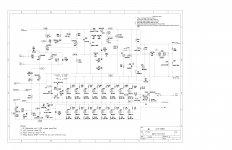
Check DC offset adjust pot for proper function and bad solder joints. It is possible that one of the FETs in the input stage is damaged though, possibly Q171. Also check the protection zeners.
The concept is not nearly as intimidating as you might think it is. The option of both balanced and unbalanced inputs makes feedback a little more complex, but all you have to do is flip the input selector switch. Then you should find that it becomes fairly conventional non-inverting opamp fare. Rf remains 100k, and Rg is 4.7k in parallel with (4.7k + 220 + 8.2k) at low frequencies, whatever that is exactly (3k-something).
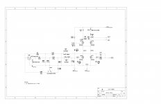
The actual amplifier circuitry is not that terribly exotic either. First you get a differential input stage (N-channel) with cascode. This then feeds a second differential amp (P-channel this time), like in a classic 3-stage amp. There is no classic VAS, instead the second differential amp (which runs substatial current) directly feeds the output stage, as seen in many MOSFET amps. The coupling is a bit oddball because of the quasicomp output.
At least it's not one of those wacky floating "upside down" circuits where the amp output is run into ground and the actual output is connected to the midpoint between the big rail decoupling caps.
The concept is not nearly as intimidating as you might think it is. The option of both balanced and unbalanced inputs makes feedback a little more complex, but all you have to do is flip the input selector switch. Then you should find that it becomes fairly conventional non-inverting opamp fare. Rf remains 100k, and Rg is 4.7k in parallel with (4.7k + 220 + 8.2k) at low frequencies, whatever that is exactly (3k-something).
The actual amplifier circuitry is not that terribly exotic either. First you get a differential input stage (N-channel) with cascode. This then feeds a second differential amp (P-channel this time), like in a classic 3-stage amp. There is no classic VAS, instead the second differential amp (which runs substatial current) directly feeds the output stage, as seen in many MOSFET amps. The coupling is a bit oddball because of the quasicomp output.
At least it's not one of those wacky floating "upside down" circuits where the amp output is run into ground and the actual output is connected to the midpoint between the big rail decoupling caps.
Thanks sgrossklass. Your suggestions were spot on, and your explanations helped me connect the dots. It turned out that the two input fets were no longer anything close to matched and a nearby diode was leaking. I matched a pair of fets and replaced the diode. I also found a burnt trace for the ground that was impossible to see without removing the the fets. I'm now getting single digit DC offset and the fix also cleared up the biasing issue.
Thanks again for the help!
Thanks again for the help!
- Status
- Not open for further replies.