Bought this broken GFA-555ii several months ago and the symptom from the seller was no sound on one channel. I checked and the fuses where missing from the DC rails for that side. Installed new fuses and powered up on DBT with no load connected. V- voltage present on the output. I refer to it as V- for the duration of this post because I'm testing this powered through a DBT which will drop the mains voltage some, so instead of the +/- 80V rails, they're more like +/- 60V.
I started probing around on the input and output assemblies looking for obvious failures. All of the output transistors on the bad channel tested fine in situ when checking for shorted outputs. The only failed component that I found was one of the VAS transistors on the input board, Q157 was shorted E to B. I went ahead and replaced all of the VAS transistors on that side with the following subs (2sa1210 -> ksa1381, 2sc2912 -> ksc3503). Powered it up on DBT, still V- present on that output.
I then started looking for other failed components in the vicinity that might be bad but so far haven't found a smoking gun.
Additional things I've done or checked:
Measurements from around the input board
OpAmps
Input board pins/test points (powered through DBT)
Thermal Transistor (transistor tested good out of circuit)
I'm starting to wonder if the opamp is bad, but I don't have any way to test it out of circuit. It doesn't blow the rail fuses or draw an abnormal amount of power as long as there is no load. I don't plan on connecting a load until I resolve the high offset issue.
Looking for any feedback on further debugging steps. Thanks so much for the help!
I started probing around on the input and output assemblies looking for obvious failures. All of the output transistors on the bad channel tested fine in situ when checking for shorted outputs. The only failed component that I found was one of the VAS transistors on the input board, Q157 was shorted E to B. I went ahead and replaced all of the VAS transistors on that side with the following subs (2sa1210 -> ksa1381, 2sc2912 -> ksc3503). Powered it up on DBT, still V- present on that output.
I then started looking for other failed components in the vicinity that might be bad but so far haven't found a smoking gun.
Additional things I've done or checked:
- Replaced diff pair (2sc2362->ksc1845) and made sure they were tightly matched. Diff pair actually tested fine once removed from circuit
- Replaced C154 (4.7uF 50V) with new. Cap wasn't bad but had 15ohm ESR
- Cleaned 2k trimpot, but haven't yet verified it sweeps cleanly across resistance range
- Checked driver transistors on output boards out of circuit, all measured good
- Checked thermal transistor on output board out of circuit, measured good
Measurements from around the input board
OpAmps
| Pin | IC101 (Good Channel) | IC151 (Bad Channel) |
| 2 (- input) | 0.06V | -0.51V |
| 3 (+ input) | 0.05V | -0.42V |
| 6 (output) | 12.19V | 0.012V |
| 7 (vcc) | 19V | 19V |
Input board pins/test points (powered through DBT)
| Pin (Good Channel) | Voltage | Pin (Bad Channel | Voltage |
| 5 | 1.78V | 7 | -57V |
| 6 | -1.78V | 8 | -57V |
| 11 | 57V | 13 | 57V |
| 12 | -57V | 14 | -57V |
| 16 | 0V | 18 | 0V |
| 17 | 1.1V | 19 | 0.01V |
| 22 | -57V | 24 | -57V |
| 23 | -57V | 25 | -57V |
Thermal Transistor (transistor tested good out of circuit)
| Pin Color | J101 (Good Channel) | J151 (Bad Channel) |
| orange | -1.1V | -57V |
| red | 1.7V | -57V |
| brown | -1.7V | -57V |
I'm starting to wonder if the opamp is bad, but I don't have any way to test it out of circuit. It doesn't blow the rail fuses or draw an abnormal amount of power as long as there is no load. I don't plan on connecting a load until I resolve the high offset issue.
Looking for any feedback on further debugging steps. Thanks so much for the help!
Well, false alarm. I continued debugging after work today and found the problem. The input board near the VAS transistors was fairly heat damaged and the traces were brittle. I lifted a trace when I replaced Q157 originally. Even though I 'fixed' it by bridging over to freshly exposed trace, that chunk of trace broke as well, probably when I was trimming the leads. I just didn't notice it until I started probing on the traces.
I green-wired from the emitter of q157 to the next solder point and now everything is working perfectly. The VAS is driving the DC offset down to 0V as expected for both channels.
TL;DR: My repair job was faulty from the beginning but I focused my troubleshooting everywhere else instead of double-checking it until i was out of ideas.
I'll leave this thread up in case it helps someone else in the future.

EDIT: My current Issue (see below) seems to be better with speakers attached. Both channels have minor turn-on thump and turn-off fizzle.
Left channel (orig. working) - DC spikes at turn-on (2-3V) and then comes right down to ~20mV and after 5 mins will bounce from 12-15mV.
Right channel (repaired) - DC spikes at turn-on (1-2V), then immediately goes to 5mV, then slowly goes down to 1mV in about 5 mins.
Any idea why they are acting different?
Tagging in on this thread - I purchased a GFA-555ii with a bad right channel.
Original symptoms: Right channel was blowing fuses and ended up having 3 shorted outputs. Resistors R164 (301r) and R174 (1k) were out of spec, otherwise everything checked out per the schematic.
Rick with Big Sky Audio was nice enough to provide his upgrade guide to the 555. So I set out to refurbish this beast.
1) Replaced all the outputs (16) with MJ21193G/94G
2) Replaced the drivers (NJW1302/3281)
3) Replaced pre-drivers (2SA1381/C3503)
4) Replaced differential pairs (KSC1845) - all matched and thermally bonded together
5) Replaced IC101 on the right channel (looked like a fake, was laser etched, not printed) Also figured it was bad with the shorted outputs
6) Replaced/upgraded the resistors and capacitors Rick suggested in his Upgrade guide
Current Issue - on Left Channel (originally working channel)
I am getting high DC offset at startup, and servo circuit seems to have trouble getting back to 0.0mV. Spikes high DC at turn on, I've seen as much as 5V but immediately goes down to 30-50mV for a couple mins, then it levels out at 1-2mV and seems to work fine after that.
After repairs/upgrades both channels started-up and bias easily. Followed the service manual process of setting bias and it all went without a hitch.
Is it possible that IC101 for the Left Channel is also bad? I didn't replace it, because I wanted to save $6, and didn't seem to be faulty when I first tested the amp with a faulty Right channel. Are there other resistors or diodes I should check? (thought I checked everything on the pre-amp board)
Last edited:
Hi,
I'm using this link to view schematic: http://akdatabase.org/AKview/albums/userpics/10004/Adcom GFA-555II Service.pdf
IMHO, the servo design is inadequate. Check voltage at pin 6 of IC101 and compare with IC with IC151. I predict both outputs will be near ground but with IC101 stuck on the ground. I further predict that if you wait until the bias settles to 1-2 mV as you described above, the IC101 will unstick from ground but still be just above 0V.
It would be better if the ICs were provided with bipolar supplies. If you confirm my suspicion, we can try a relatively easy remedy.
Here are the voltages - using speaker ground.
IC101 (bad channel) - spikes to 6V, then immediately comes down to 4.6V and slowly decreases over 5 mins to 3.960V
IC151 (good channel) - spikes to 6V, then immediately comes down to 4.4V and slowly decreases over 5 mins to 4.089V
I checked these voltages previously and couldn't see anything conclusive - hopefully it means something to you
FYI - other PIN voltages after warm-up IC101/151
Pin 1 - 13mV/12mV
Pin 2 - 66mV/41Mv
Pin 3 - 44mV/29mV
Pin 4 - 0mV/0mV
Pin 5 - 12mV/12mV
Pin 6 - see above
Pin 7 - 19.45V/19.70V
Pin 8 - 62mV/61mV
Well, that puts a bullet in my servo deficiency accusation. The bias resistances into the input pair (R104 and R124) are dramatically different and would yield a negative amp offset error if not for the servo correction; so I retract my previous assertion. The servos should force amp offset errors to a few mV immediately and remain there; there shouldn't be any 5 minute stabilization period required. Drift of the opamp output is normal as the servo accommodates PA drift.
However, the opamp offset errors (difference between pins 2 & 3) seems unusually large, so I am suspicious of the opamps. I suggest measuring differentially between pins 2 & 3 for a more direct measurement of opamp offset error. Any voltage larger than 10mV would be excessive.
Rather than buy replacement opamps from Adcom, I'd get a couple of TL071. Replace IC101 first, and then IC151 if you're pleased with results.
Good luck!
Last edited:
Unsure what you mean by "I suggest measuring differentially between pins 2 & 3 for a more direct measurement of opamp offset error."
Do you mean use DMM probes on pins 2 and 3? Once I confirm the specific measurement, I can check this and see if it sheds light on the problem.
I did go back and measure every resistor and diode again, comparing to the schematic and to the other channel - nothing is out of spec.
I might have a couple TL071s laying around here.... hmmmm.
Well, that was anti-climactic - I measured both ICs across Pin 2 and 3, not sure if this tells us anything, because both channel look to be working.
IC101 - spikes to 180mV then within 7 secs settles at 0mV
IC151 - spikes to 175mV then within 7 secs settles at 0mV
IC101 - spikes to 180mV then within 7 secs settles at 0mV
IC151 - spikes to 175mV then within 7 secs settles at 0mV
Been going through Hoppe's Brain website for some possible clues. I found a mention to know the health of the servo, measure the output current.
I measured the voltage from Pin 6, going across 1.5M resistors R126 and R176 to compare the two channels. R126 measures 1.513M and R176 measures 1.498M.
R126 (Left - bad) - starts out at 4.1V but drops quickly to 3.8 and continues over 2 mins until stabilizing at 3.34V (current = 2.208uA)
R176 (right - good) - starts out 4.2V and drops at a steady rate for about 2 mins and stabilizes at 3.63V (current = 2.423uA)
Website doesn't mention how much current is the right amount and both of these seem fairly close, starting to wonder if there is a problem, or if this is normal behavior from this model of amp?
The opamp output voltages look good. They are both well clear of the supply rails, all that's necessary.
What's more important are the amp output voltages. They should be only a few mV, should settle quickly, and should change very little.
Bias current in the output stages should be a completely separate issue.
What's more important are the amp output voltages. They should be only a few mV, should settle quickly, and should change very little.
Bias current in the output stages should be a completely separate issue.
I was not trying to measure bias current in the output, I was trying to measure the output current from the servo IC. Before I go to all the trouble of removing the pre-amp board from the chassis and change out the IC, I was trying to confirm the IC is faulty, or if this behavior is "within spec".
Here is the statement from the Hoppe's Brain website -
Here is the statement from the Hoppe's Brain website -
- Low DC offset from the speaker terminals. This indicates good matching of the input transistors, and is generally a sign of good health. Incidentally, the GFA-555 MKII has a DC servo, so will show very low DC offset, even with poorly matched input transistors. In such an amp, the output current from the DC servo can tell you how well balanced the amp is.
Be sure to check the DC offset for each channel at the speaker terminals with NO speakers attached. The offset should be low within seconds of turn on. The original ADCOM spec was 100mV or less but will typically be much lower like less than 10mV.
1) How did you match the input pairs? They need to be checked on a jig fed with steady DC voltage and carefully controlled temperature. I would swap the originals back in for the channel that worked well originally before all the parts changes. See what the offset is without speakers and before changing anything else.
2) What part number were the original servo ICs? They should have been ADCOM 3A or sometimes LT1006. I believe your servos are working but there is a possible imbalance somewhere.
3) When replacing output transistors, did you check all .22 ohm emitter resistors?
4) Check R104 (L ch) and R154 (R) for 100 ohms.
5) For shutdown noise, replace R801~R804 with 3.9k, 2W, 5% Yageo metal oxide resistors (move to top side of pc board).
When powering up the GFA-555II, you will normally hear a pop which is normal as there is no speaker relay protection with delay for isolation during power on/off conditions. The current GFA-555SE model has added speaker protection along with balanced inputs and a few component changes.
Thanks for the reply Rick - here's some additional context to your questions/suggestions.
Be sure to check the DC offset for each channel at the speaker terminals with NO speakers attached. The offset should be low within seconds of turn on. The original ADCOM spec was 100mV or less but will typically be much lower like less than 10mV.
- I checked Left channel, having removed the right channel fuses, it had ~50-mV of DC 1-2 secs after startup that very slowly went down to about ~15mV (similar to the current issue I'm trying to resolve)
1) How did you match the input pairs? They need to be checked on a jig fed with steady DC voltage and carefully controlled temperature. I would swap the originals back in for the channel that worked well originally before all the parts changes. See what the offset is without speakers and before changing anything else.
- I matched the KSA1845s with a Chinese multi-tester and while I know it's not ideal, I assumed it would get me close enough for the servo to correct. I checked 15 transistors and matched them for Hfe and Vf for 4 with exact same specs and the ones for the right channel work perfectly.
2) What part number were the original servo ICs? They should have been ADCOM 3A or sometimes LT1006. I believe your servos are working but there is a possible imbalance somewhere.
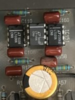
- they were both LT1006 ICs, but the left channel looked like a fake (laser etched not printed), so I replaced it. (See pic below - middle is possible fake I removed so you can see all three)
3) When replacing output transistors, did you check all .22 ohm emitter resistors?
- I tested all emitter resistors
4) Check R104 (L ch) and R154 (R) for 100 ohms.
- I checked these, as well as all resistors on the pre-driver board and replaced a 301R and 2-1k resistors that were out of spec
5) For shutdown noise, replace R801~R804 with 3.9k, 2W, 5% Yageo metal oxide resistors (move to top side of pc board).
- I will check on this, the shut-down is barely a turn-off pop, so not too worried about that behavior right now
When powering up the GFA-555II, you will normally hear a pop which is normal as there is no speaker relay protection with delay for isolation during power on/off conditions. The current GFA-555SE model has added speaker protection along with balanced inputs and a few component changes.
- there is a noticeable thump, but mostly in the right channel and it sucks in the woofer, because of the immediate -6V DC, then decreases immediately.
Be sure to check the DC offset for each channel at the speaker terminals with NO speakers attached. The offset should be low within seconds of turn on. The original ADCOM spec was 100mV or less but will typically be much lower like less than 10mV.
- I checked Left channel, having removed the right channel fuses, it had ~50-mV of DC 1-2 secs after startup that very slowly went down to about ~15mV (similar to the current issue I'm trying to resolve)
1) How did you match the input pairs? They need to be checked on a jig fed with steady DC voltage and carefully controlled temperature. I would swap the originals back in for the channel that worked well originally before all the parts changes. See what the offset is without speakers and before changing anything else.
- I matched the KSA1845s with a Chinese multi-tester and while I know it's not ideal, I assumed it would get me close enough for the servo to correct. I checked 15 transistors and matched them for Hfe and Vf for 4 with exact same specs and the ones for the right channel work perfectly.
2) What part number were the original servo ICs? They should have been ADCOM 3A or sometimes LT1006. I believe your servos are working but there is a possible imbalance somewhere.
- they were both LT1006 ICs, but the left channel looked like a fake (laser etched not printed), so I replaced it. (See pic below - middle is possible fake I removed so you can see all three)
3) When replacing output transistors, did you check all .22 ohm emitter resistors?
- I tested all emitter resistors
4) Check R104 (L ch) and R154 (R) for 100 ohms.
- I checked these, as well as all resistors on the pre-driver board and replaced a 301R and 2-1k resistors that were out of spec
5) For shutdown noise, replace R801~R804 with 3.9k, 2W, 5% Yageo metal oxide resistors (move to top side of pc board).
- I will check on this, the shut-down is barely a turn-off pop, so not too worried about that behavior right now
When powering up the GFA-555II, you will normally hear a pop which is normal as there is no speaker relay protection with delay for isolation during power on/off conditions. The current GFA-555SE model has added speaker protection along with balanced inputs and a few component changes.
- there is a noticeable thump, but mostly in the right channel and it sucks in the woofer, because of the immediate -6V DC, then decreases immediately.
Attachments
When checking DC offset you do not have to remove any fuses.
The original servo IC was probably fine. It does not have to be a fast high speed opamp for the job it has. I wonder why someone would counterfeit an LT1006 as it is not exactly a high profit part.
If it were me, I would purchase input pairs from Phloodpants as I know he would match them well and there would be no worries. He and anatech have written extensively on good transistor matching.
A multimeter may give you a general idea of a ballpark match but hardly sufficient enough. Temperature is very important because just handling a transistor with your fingers will raise its temperature. All parameters must be the same or else measurements will be skewed.
How close were your matches? 10%, 5%?
Do you have any thoughts on BSST saying I could use a TL071P as an IC substitute (since I have those on hand)? I would probably put in a socket, if it doesn't work well though.
You're probably right, spending $20 is not much to have confidence in the input pair.
My process is my own (in that it has no rhyme or reason except in my mind). I test the part with two different multi-testers (get on eBay or Amazon for $15, then I take the closest matches for both Hfe and Vf f. I only tested 15 KSC1845s, because they were so close with this testing I had 2 good pairs (+/-3%) so I didn't bother testing any more. I also have a B&K 815 multimeter which can test Hfe - maybe I should run the close matches on this as well and see how close I can get?
I will be the first to say that I should build a testing jig and do it the right way, but this is only the third time I have had to have matched parts, most of the amps I have built either didn't need this accuracy, or I got lucky with my testing methodology.
Latest update - some good news.
Took it apart tonight and replaced the Left Channel input pair (Q101/102). I matched another 10 KSC1845s, this time with my multi-tester first for Hfe and Vf and then tested again for Hfe with my B&K 815. I took the best matched pair out of the group.
Multi-tester measured HFE at 435/435, Vf at 671/670
B&K 815 multimeter measured Hfe at 449/449)
For both channels input pairs, I mated them face to face, with a tiny amount of thermal paste and heat shrink together to keep the faces in contact - looks like a spider, one bent backwards face up, one bent forward face down. Not sure it helps much, but I always make things more difficult than needed.
Good news:
Turn on thump is almost gone, now at turn-on it only spikes to -4V (was -6 to 7V), but it goes down much faster to <100mV so fast I had to use the high/low on my meter to catch it. Also the turn-off is a small "click" noise after ~30 secs after power down. So this has helped both on and off noises.
DC offset progression:
Start-up = -4V (maybe 1/2 sec), Drops to ~50mV immediately (1-2secs later), Steady drop to ~20mV (30-45secs later) and finally drops to ~1mV (~10-12 mins from turn-on). All of these are lower, and drop faster with less fluctuation than it did before changing the input pair.
Gain:
Right = 27.273 and Left = 27.275 - So they both appear to work great reproducing a 1k signal tone.
I will give it a day or two of listening and if I have any other unresolved problems I will buy some matched inputs from Hoppe's Brain website.
I think I can make sense of much of the turn-on transient.
Assuming Q101 shares current equally with Q102, its collector current will be about 1mA, and its base current will be about 2.2uA. The source resistance is roughly 100K (R102), so the Q101 base voltage will be about -220mV. (IC101 output will be initially 0V and I'm treating bias error at Q102 as negligible compared to Q101.) Gain of the amp is about 23.1 V/V. So at power application, initial output would be about -5.1V and so the initial transient you observe seems reasonable. Servo feedback then drives the offset toward 0. I can only guess about warmup drift.
The LT1006 has great voltage offset error, better than TL071, but is has larger bias current and the ADCOM amp uses relatively large 4.7M resistors (R125, R127). Typical 8nA bias current will develop about 38mV across the 4.7M base resistors. Further, the data sheet notes some warmup drift in the first minute. Perhaps these issues are in play.
In any event, it's all kind of academic. You've done a great job! Enjoy!
@BSST thanks for the education on the circuit and the inner workings, still over my head to do all of that just looking at the schematic..
I may still replace IC101 - because I still can't understand why the right channel (IC151) is straight line, no fluctuation from start-up spike to <10mV in 5-10secs and then very linear down to 1mV within 1-2 mins. Bothers me that the left has much higher DC and fluctuates for a few minutes before settling and then takes 10 times longer to finally get to 1mV.
I have been listening for a little while and it does sound great - no issues with the sound. Probably more my OCD than a real problem, IDK.
It's hard to imagine anything other than IC101 as the culprit, but there's one last test you could try for confirmation.
Note that R175 and R177 sense ground and the amp output, respectively. Use your voltmeter to probe directly on the resistor leads. You should see exactly the same behavior on the resistor leads as you observe across the speaker terminals; it's another way of saying there should be no voltage drops between the resistor leads and their respective ground and output connections. If you see any differences, it's an indication of a marginal connection or unfortunate PCB trace routing.
If you ultimately try a TL071, a socket seems like a good idea. Also, confirm about 20VDC on pin 7 of the IC. R179 provides very light supply current. You could tack in an additional 33K in parallel or other remedy. The C159, R179 time constant seems lengthy, an unimportant curiosity.
Good luck!
Best,
Steve
- Home
- Amplifiers
- Solid State
- Adcom GFA 555ii with high dc offset on one channel (V-)