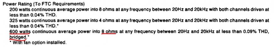
The amp works great in stereo.
Clips at 210 watts both channels driven at 1kHz.
I've been listening to the amp for about a year now. I purchased it non-functioning on ebay. Replaced 3 or 4 transistors (I forget which ones) and the small electrolytic caps. THD is good on both channels. So are DC offset and bias adjustments.
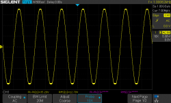
I decided to put it on the bench again and test it in bridged mode.
With the input at about 275 mV and an output of just under 20 watts it begins to clip, see the attachment below.
I haven't started probing thru it yet, because I have some questions.
Can some one point out the signal path in bridged mode? It looks like the only signal going to the right channel is from the left channel feedback. Is that correct?
Doesn't the right channel signal need to be inverted somewhere?
I read thru the service manual but it doesn't describe the operation in bridged mode.
Has anyone come across this before?
Thanks
Gary
Clips at 210 watts both channels driven at 1kHz.
I've been listening to the amp for about a year now. I purchased it non-functioning on ebay. Replaced 3 or 4 transistors (I forget which ones) and the small electrolytic caps. THD is good on both channels. So are DC offset and bias adjustments.
I decided to put it on the bench again and test it in bridged mode.
With the input at about 275 mV and an output of just under 20 watts it begins to clip, see the attachment below.
I haven't started probing thru it yet, because I have some questions.
Can some one point out the signal path in bridged mode? It looks like the only signal going to the right channel is from the left channel feedback. Is that correct?
Doesn't the right channel signal need to be inverted somewhere?
I read thru the service manual but it doesn't describe the operation in bridged mode.
Has anyone come across this before?
Thanks
Gary
Attachments
Last edited:
VERY simple instructions on bridging with colored pictures-
How to Bridge an Amplifier: 7 Steps (with Pictures) - wikiHow
How to Bridge an Amplifier: 7 Steps (with Pictures) - wikiHow
Either my coffee hasn't kicked in yet, or I don't understand bridging 😕
I assume the illustrated amp has single-ended outputs, so the "-" outputs are at zero volts (probably grounded). If grounded then no bridging is taking place at all. To bridge, you would need to feed the "-" input of the amp with the inverted signal of the "+" input, then connect the speakers to both "+" outputs
A and C. The connection shown does nothing, right?
Mike
Yes you are right, papa (Nelson) used the feedback from one channel (via 22k resistor) to drive the feedback of the other channel whose input was grounded, given that the feedback goes into a "differential" pair, you get a negative swing on that channel. e.g. 40v output on channel A is reduced to 1.2v (made up number) at its feedback, in reality this causes a negative 1.2v on the LTP/ Differential, in other words an inverted 180 degree out of phase signal. Why not use this 180 degree out of phase signal to feed the second channel and drive that out of phase to be able to bridge the two?
For this to work, not only do u need to connect the nfb of A to B, but also short the input of B to ground since you don't want to amplify anything else on B.
I have worked on the 555 mark2. They seem to clip much higher... something in the order of 270-290 watts. They were quite underrated.
For this to work, not only do u need to connect the nfb of A to B, but also short the input of B to ground since you don't want to amplify anything else on B.
I have worked on the 555 mark2. They seem to clip much higher... something in the order of 270-290 watts. They were quite underrated.