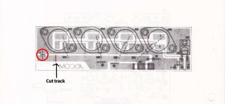
The scratched copper is the power rail connection to the cap. It's the trace connected to the transistor collectors.
I want to understand well: can you confirm these steps for me? The positive of one capacitor on the V+ of the scratched board, while the other capacitor has the negative on the V- of the scratched board? It's correct? As you can see from my attachment: should the track be cut where the masses go? One last question: what changes in terms of sound with this modification? ThanksThe scratched copper is the power rail connection to the cap. It's the trace connected to the transistor collectors.
Attachments
Hi CalebLost,
Sorry, I didn't answer to this because I don't modify these amplifiers. You don't really gain any worthwhile performance gain with many modifications. Some you do but the average person can't sort that out and everyone is an expert.
However, this may help you. A bypass capacitor is generally connected between each supply rail and the "dirty ground". So one from the positive rail voltage (collectors of the NPN transistors in this case) to the ground - or should we actually call it "common". The other from the negative rail voltage ot the collectors of the PNP transistors. Now, it is very important to remember that the collector of an output transistor is not always connected to the supply rails! In this amplifier they are.
These capacitors will conduct noise currents, and therefore the common point should go the the main filter capacitor common point alone. That's why we call it "the dirty ground". I don't like calling the common point "ground" at all. They are each different even though they measure short with a normal ohmmeter. Keep them different in your mind! Connecting these ot the wrong ground can greatly degrade performance.
-Chris
@anatech
Hi Chris, Thanks for the reply. To be brief: so you don't recommend making this change? I saw it in the MKII version together with the capacitors on the driver board. I had the Adcom GFA 555 MKII and never liked it, in fact I kept the original Adcom GFA 555. After reading your answer I ask myself: why make a modification (in this case to a power amplifier) if there are no benefits in the sound? In my Adcom GFA 555 I changed: the four original capacitors, I rewired everything, I changed the Toshiba ones with the Onsemi ones, I checked and adjusted the bias. I believe this is the most that can be done to freshen up the power amp and maintain the originality of Nelson Pass. I read about many modifications, but the question is always the same: does it improve the sound? If the answer is "no" why should I do it. Forgive my bad English.
Hi Chris, Thanks for the reply. To be brief: so you don't recommend making this change? I saw it in the MKII version together with the capacitors on the driver board. I had the Adcom GFA 555 MKII and never liked it, in fact I kept the original Adcom GFA 555. After reading your answer I ask myself: why make a modification (in this case to a power amplifier) if there are no benefits in the sound? In my Adcom GFA 555 I changed: the four original capacitors, I rewired everything, I changed the Toshiba ones with the Onsemi ones, I checked and adjusted the bias. I believe this is the most that can be done to freshen up the power amp and maintain the originality of Nelson Pass. I read about many modifications, but the question is always the same: does it improve the sound? If the answer is "no" why should I do it. Forgive my bad English.
Hi CalebLost,
Well, I didn't say it for sure will not improve anything, but I have not done this.
I'm not convinced that replacing good main filter capacitors does anything. If they are bad - yes, otherwise no. The outputs Adcom used were fine. I wouldn't have replaced them unless a customer insisted. I just want to make sure they are matched - either brand. Because the new OnSemi outputs (MJ2119x) have better gain vs collector current behavior they may result in lower distortion at higher power levels. However this difference is reduced by the voltage amp stages and I doubt that practically, you would hear it compared to the increased distortion of the loudspeaker at higher powers.
You always have to weigh real benefits against the practical improvements. Then, will you actually hear anything (don't forget about expectation bias). With crappy outputs - yes. There may be an audible difference to the positive. In theory - yes there may be. But once you apply corrective feedback, the differences are greatly reduced. As they should be because of the way the circuits work.
I am not saying you can't improve an amplifier. I do it every day, but only some can be improved. Others really will never perform well. In addition, the things that do improve sound are seldom posted. I don't post them. Other improvements involve the use of expensive test equipment, matching components and using certain component types because of their characteristics. There is no "best capacitor" for example.
- Best, Chris

- Home
- Amplifiers
- Solid State
- Adcom GFA-555 mk1 Bypass Cap Process Check