Hi all,
I'm relatively a new member and forum lurker and have generally found answers to my questions by simply searching the respective boards, but haven't found a specific thread that addresses this problem directly and specifically to my issue.
Here's the question?
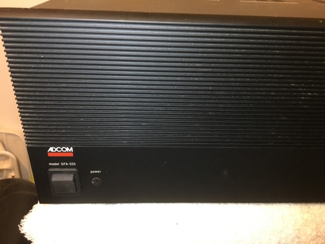
I have an Adcom GFA-555 that I'm trying to figure where to start with a high DC-offset.
Both speaker output channels are reading about 8.23 & 8.35 vdc.
Not the 82.00 vdc I see in most of the threads I've searched.
Anybody have any pointers in directing me to where to start and what to look for first.
I have an oscilloscope and DMM.
And yes I understand about the high voltages and current.
TIA
I'm relatively a new member and forum lurker and have generally found answers to my questions by simply searching the respective boards, but haven't found a specific thread that addresses this problem directly and specifically to my issue.
Here's the question?
I have an Adcom GFA-555 that I'm trying to figure where to start with a high DC-offset.
Both speaker output channels are reading about 8.23 & 8.35 vdc.
Not the 82.00 vdc I see in most of the threads I've searched.
Anybody have any pointers in directing me to where to start and what to look for first.
I have an oscilloscope and DMM.
And yes I understand about the high voltages and current.
TIA
Okay, after searching further here on the forum I found a link to a GFA-555 schematic and will be able to delve into this a little further.
I think I should be okay now.
I think I should be okay now.
Well I got this $10 yard sale Adcom amp up and running and it's in perfect spec now and making music.
Did some heavy visual inspecting and a little bit of initial testing with my DMM and couldn't find anything that was obviously wrong with my very novice skill set.
So when I initially got the amp from the lady at the yard sale she didn't have a clue as to whether it was working or not. She stated that it was left in the basement of their rental property that they were putting up for sale and made no guarantees about its condition.
I did plug it in at her residence and saw it powered up but that was the extent of things. I paid her $10 and drove off.
Got home and checked the bias and it was in spec so I then tried to play some music through it on some junk Sony speakers and it made no sound at all through either channel.
I just assumed that the fuses were good because all 4 on the output boards looked to be in great shape visually as I didn't see the filament being damaged, but guess what when I inspected them further with my DMM the two outside board fuses were NG.
The filament looks perfect but they were both open.
Replaced them with new ones and the amp is running with 0.6mv on the left and 0.14 on the right.
Sometimes it the most overlooked simple stuff.
I hope this helps someone else (another newb like me) down the road.
Glass fuses sometimes fail due to the "filament" detaching from the end caps.
I've seen this happen plenty of times with equipment brought into my shop.
Always best to check for continuity and don't go by appearances.
I've seen this happen plenty of times with equipment brought into my shop.
Always best to check for continuity and don't go by appearances.
Glass fuses sometimes fail due to the "filament" detaching from the end caps.
I've seen this happen plenty of times with equipment brought into my shop.
Always best to check for continuity and don't go by appearances.
That’s exactly what appears to have happened.
I just went by the visual appearance of the fuses and proceeded from there thinking something else was wrong.
I did find it odd that with the two fuses being open that I was getting 8.XX vdc on both speaker terminals.
It was completely throwing me off.
That’s exactly what appears to have happened.
I just went by the visual appearance of the fuses and proceeded from there thinking something else was wrong.
I did find it odd that with the two fuses being open that I was getting 8.XX vdc on both speaker terminals.
It was completely throwing me off.
Those Adcom "555" amps require some careful attention and modifications to insure long life.
There's several things that are in my opinion, potential problems, some due to aging, others that are due to design flaws/cutbacks.
I don't know if yours has the "optionl fan kit", but the ones I've serviced all suffer from overheated parts/boards, and lacking any heatsinking of the driver transistors.
I've had to custom design and install heatsinks, and design a silent fan system for some airflow in that enclosure.
There is other things, but I'm not going into it all, the web has that information.
Hi,
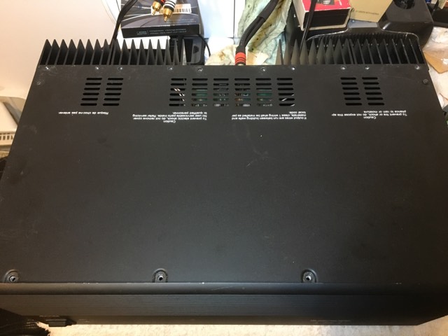
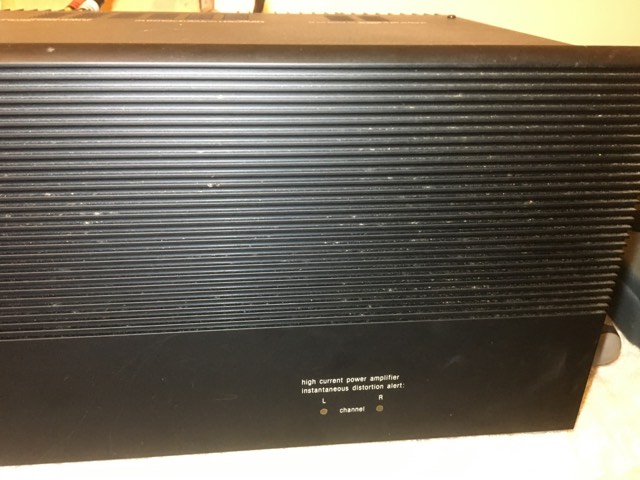
Not seeing any type of fans in this unit. I did read about not having any type of speaker protection in this particular amplifier.
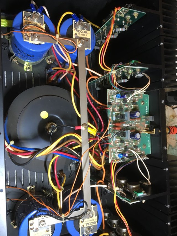
I did visually inspect all the PCB boards and didn't see or notice anything obvious that has indicated any over heating around the resistors.
Honestly, I was pretty surprised as to how clean this amp was internally. The pictures attached show the unit in its current condition without any kind of cleaning by me.
I tested the power supply capacitors with my LCR meter and those 4 capacitors are in perfect spec.
I'm inclined to believe that the previous owner put this amp on the shelf when the fuses failed and never touched it again.
I'm going to swap out the front end board electrolytic caps and button it up and use it as is.
But I 'm open to any suggestions on improving the amp since I have only $10 invested and about $8 in fuses.
Hello,
If you want to put some time and money into your 555, I highly recommend checking out the upgrade kits by Chris over at Hoppe's Brain.
I recently went through one of my 555's and installed one of his power supplies, input boards, upgraded driver transistors, added local bypass caps to the output boards,and replaced all of the output transistors.
The amplifier sounds great and will probably outlive me��!
Dan
Hello,
If you want to put some time and money into your 555, I highly recommend checking out the upgrade kits by Chris over at Hoppe's Brain.
I recently went through one of my 555's and installed one of his power supplies, input boards, upgraded driver transistors, added local bypass caps to the output boards,and replaced all of the output transistors.
The amplifier sounds great and will probably outlive me��!
Dan
Yes, I found his site and various Adcom amplifier upgrade solutions to be quite interesting. I have another one of these same Adcom GFA 555's that already has the the matched differential pairs he sells and Mouser driver transistors upgrades.
I'm most like going to the same simple mods to this one now since it's fully functional and use these as a matched pair of mono block amps.
Can you tell me the logic behind the bypass caps?
Since the output boards are fed rail voltage/current through long wires, it increases the power supply impedance. The wiring adds some inductance and can pick up noise.
The local bypass caps added to the output boards supply quick "bursts" of current when needed and help filter noise (they are 100uf/160V Panasonic EE caps and are bypassed with 0.1uf high voltage film caps).
Since the input board is feed its power on the 555 mk1 from the output boards, this is the first stage in supplying clean power to the input circuitry. The updated input board also has its own local bypass caps.
Of course, people can argue until the cows come home if this all really helps with the performance of the amplifier, but it is pretty standard in higher performance amplifiers.
Interestly, Adcom actually implemented these changes in the Mk2 version of the 555.
Dan
Since the output boards are fed rail voltage/current through long wires, it increases the power supply impedance. The wiring adds some inductance and can pick up noise.
The local bypass caps added to the output boards supply quick "bursts" of current when needed and help filter noise (they are 100uf/160V Panasonic EE caps and are bypassed with 0.1uf high voltage film caps).
Since the input board is feed its power on the 555 mk1 from the output boards, this is the first stage in supplying clean power to the input circuitry. The updated input board also has its own local bypass caps.
Of course, people can argue until the cows come home if this all really helps with the performance of the amplifier, but it is pretty standard in higher performance amplifiers.
Interestly, Adcom actually implemented these changes in the Mk2 version of the 555.
Dan
Thanks for the information Dan.
Could this bypass capacitor upgrade be more relevant when the 555 is being used in bridged mode?
To be honest I’ve heard the 555 ll and couldn’t hear any difference in that amp and the first generation.
Of course that’s based on my own personal and subjective listening experience.
Others people mileage may vary.
- Home
- Amplifiers
- Solid State
- Adcom GFA-555 High DC Offset Question?