Hi all,
Is it possible to bias a 555 in class A? And would it be safe? Even less than 30w pc would be enough...
Thanks
Is it possible to bias a 555 in class A? And would it be safe? Even less than 30w pc would be enough...
Thanks
it must be some language barrier 🙂
ever seen Treshold papers for biasing procedure?
I've just posted one yesterday
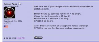
If amplifier is properly functional, besides temperature you don't need any other parameter ........ in fact , you need voltmeter to check on appropriate place, to ensure same Iq for both channels ......
Contrary to amplifiers working in B (AB) Class, where you need a scope and DVM to see/set to some prescribed more or less magical value, here you are asking about simple cranking of Iq ...... and looking at schematic and overall physical layout of amplifier itself, first boundary you're having is heatsinking capacity
so, conclusion is simple - temperature is your criteria
ever seen Treshold papers for biasing procedure?
I've just posted one yesterday
If amplifier is properly functional, besides temperature you don't need any other parameter ........ in fact , you need voltmeter to check on appropriate place, to ensure same Iq for both channels ......
Contrary to amplifiers working in B (AB) Class, where you need a scope and DVM to see/set to some prescribed more or less magical value, here you are asking about simple cranking of Iq ...... and looking at schematic and overall physical layout of amplifier itself, first boundary you're having is heatsinking capacity
so, conclusion is simple - temperature is your criteria
You should decrease your power supply voltage to decrease the output transistors power dissipation for a given bias current. Best way is to replace your power transformer.

You should decrease your power supply voltage to decrease the output transistors power dissipation for a given bias current. Best way is to replace your power transformer.
Short of that, you can get a second transformer with the same secondary current rating and the voltage you want to reduce by. Wire it out of phase with the Adcom's power transformer secondary, just before the bridge. You'll need a second transformer with a center tapped secondary...
Why this approach? The voltage reducing transformer will be cheaper than a whole new PT. You can more easily put everything back to original (reconnect 3 wires...) if the high Iq biasing idea doesnt work out.
If you happen to have a transformer with a little more secondary voltage than you'd ever want to reduce by, you could hook it up in this way and then using a variac, empirically determine the best power supply reduction voltage for the Iq you wish to set. Then buy a more permanent solution.
I don't expect it to work if you are on 220v ac power...
Yes, what a stupid I was... We have 230v, so I will double ac out using 110v tap
You could put the amp on a Variac - the only problem being that if it went
straight into the wall the amp would get very hot.

straight into the wall the amp would get very hot.
if you want simplest - no other change except increase Iq up to palm rule
if you want go further, change of mains xformer
but, accounting on needed output power, heatsinking capacity (W) and reasonable dissipation per output part
if you want go further, change of mains xformer
but, accounting on needed output power, heatsinking capacity (W) and reasonable dissipation per output part
Looking at the transformer schematic there are 2 primary windings one with a 0v,20v,120v and the other with a 0v,100v, and 120v. You could connect the two 120volt primaries in series which would be the white wire to the black wire. Apply your 220 vac to the blue wire and yellow wire.
Hi all,
Is it possible to bias a 555 in class A? And would it be safe?
It already has a tiny amount of class A, so why don't you figure out how much and then get back to us?
What would be the minimum rail voltage before the main board circuits would stop functioning as intended? Or if the rails were reduced to 36v, approximately 45% lower, then could one reduce all the main board resistor values by 45% ? On the outputs I'm Using MJE21193,21194 which can manage 5A continuous, so potentially as high as 2.5A bias ?
- Home
- Amplifiers
- Pass Labs
- Adcom GFA-555 class A biasing